The BM-24 fighting vehicle was designed to suppress and destroy enemy fortifications, strongholds and resistance units, destroy and suppress artillery and mortar batteries, destroy and suppress enemy manpower and equipment in areas of concentration.
During development, the system was designated "M-31A". The development was carried out on the basis of tactical and technical requirements №007 for the "M-31A" rocket system of the 4th Directorate of the Main Artillery Directorate of the Armed Forces, approved by the Commander of the Armed Forces' Artillery, Chief Artillery Marshal Voronov on 25.04.1947.
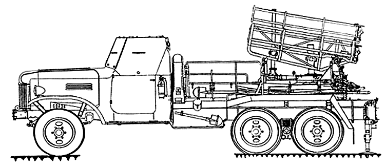
BM-24 (GAU index - 8U31) was created in the State Security Service Spetsmash (former SCB at the plant "Compressor", Moscow) under the leadership of V.P. Barmin. ZIL-151 (ZIL-151) was adopted as the chassis of the combat vehicle. One of the designations of the prototype was PUO-44.
Military testing of the M-31A system - the future M-24 with the BM-24 combat vehicle and 240.6 mm turbojet shells was carried out from July 25 to August 31, 1950 at the State Central Range (GCT) (Kapustin Yar) under the leadership of Lieutenant-General of Artillery SF Nilovsky . For this purpose four prototypes of the BM-31A fighting vehicle and 1000 M-31A rockets were delivered to the range. In addition, for the purpose of comparative tests, 4 BM-31-12 and 325 M-31UK combat vehicles with GVMZ-1 fuses were delivered to the GSC. The goals and objectives of the tests were referred to:
- to check the combat, technical and performance characteristics of the system and their compliance with tactical and technical requirements;
- to determine the ability to engage and destroy well concealed targets (manpower and material in the trenches) within the full range of fire at various angles of vertical and horizontal firing, as well as the suppression and destruction of strongholds.
- Determination of the reliability and effectiveness of the M-31A projectile with the B-361 fuse is convenient for their operation during firing and transportation.
- identification of structural, operational and ballistic advantages and disadvantages of the BM-31A combat vehicle, M-31A projectile and B-361 fuse in comparison with the standard BM-31-12 with the M-31UK projectile and GVMZ-1 fuse.
- Issuance of a conclusion on the expediency of the Soviet Army's adoption of the BM-31A, the M-31A and the B-361 fuse to replace the standard BM-31-12, the M-31UK and the GVMZ-1.
As part of the tests, the run of combat vehicles in loaded condition and comparative firing were carried out. Mileage tests of combat vehicles and projectiles were successful.
After conducting all necessary tests and repeated amendments to the Ordinance on Adoption into Service, the latter was signed in February 1951. At the same time the works on organization of serial production of shells, fuses and combat vehicles of the new M-24 system were unfolded. According to other data, the system was adopted for service of the Soviet Army on the basis of the Council of Ministers Decree № 875-441ss of 22.03.1951. The production of combat vehicles was carried out at the plant named after M.V. Lenin. Karl Marx plant. It was probably one of the factories.
The system became the first post-war system adopted by the Soviet Army, which was part of the firing power of the USSR and later of foreign countries: West Germany, Egypt (United Arab Republic) (including M-24F (index F-961) and M-24FUD (index F-961U) shells, Cuba, Poland, North Korea, Syria, Somalia, Israel (captured as a trophy and at least a shell was produced), Angola, Mozambique and probably others. In the mid-1980s, the system was still in service with the Soviet Army and produced the BM-24 combat vehicle (index 8U31) and projectiles.
BM-24 combat vehicles were part of brigades (regiments) of corps subordination. Totally there were 54 BM-24 combat vehicles in the small arms or mechanized corps.
In 1951, at Plant № 121 (now JSC "Bryansk Red Banner of Labor Chemical Plant named after 50th Anniversary of the USSR") the production of M-24F turbojet projectile was mastered.
In addition to the BM-24, the BM-24T combat vehicle on the chassis of the AT-C medium tracked artillery tractor (product 712) was created for 240-mm turbojet shells. The BM-24T fighting vehicle was put into service with the tank corps of the Soviet Army. Compared with the wheeled combat vehicle, the BM-24T was more expensive, had a lower speed on the highway and a reduced motor resource. On the other hand, having a high cross-country ability, it was able to operate as part of the tank unit in conditions of complete off-road capability. The principal difference between the BM-24T and BM-24 was the replacement of the honeycomb rails by tube rails.
In the explanatory note of the Deputy Chief of the GAU Major-General of Engineering and Technical Service A. V. Bogdanovich. Sokolov of December 11, 1952 provides data that in addition to the plan of development and research on land-based reactive armament for 1952-1953, which was under consideration in the Council of Ministers of the Union of Soviet Socialist Republics, it was proposed to develop a combat vehicle BM-24 on the basis of a floating tracked armored personnel carrier designed for firing 240 mm turbojet shells M-24F. This work was singled out for inclusion into the 1953 draft plan by the Deputy Military Minister Lieutenant-General of the Tank Forces Comrade Vershinin V.G. due to the need of armoured and mechanised troops for powerful and fast tracked reactive systems capable of accompanying armoured and mechanised units.
In November 1952, a draft of the theme was prepared: "Combat vehicle BM-24P based on a floating tracked armored personnel carrier (object 750)" for firing turbojet shells M-24F.
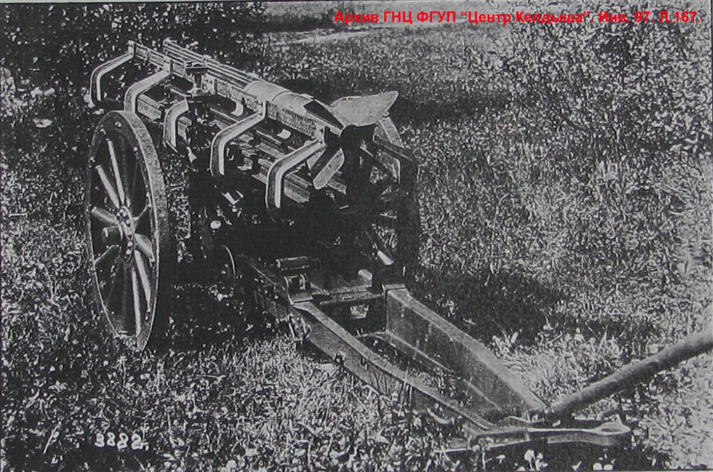
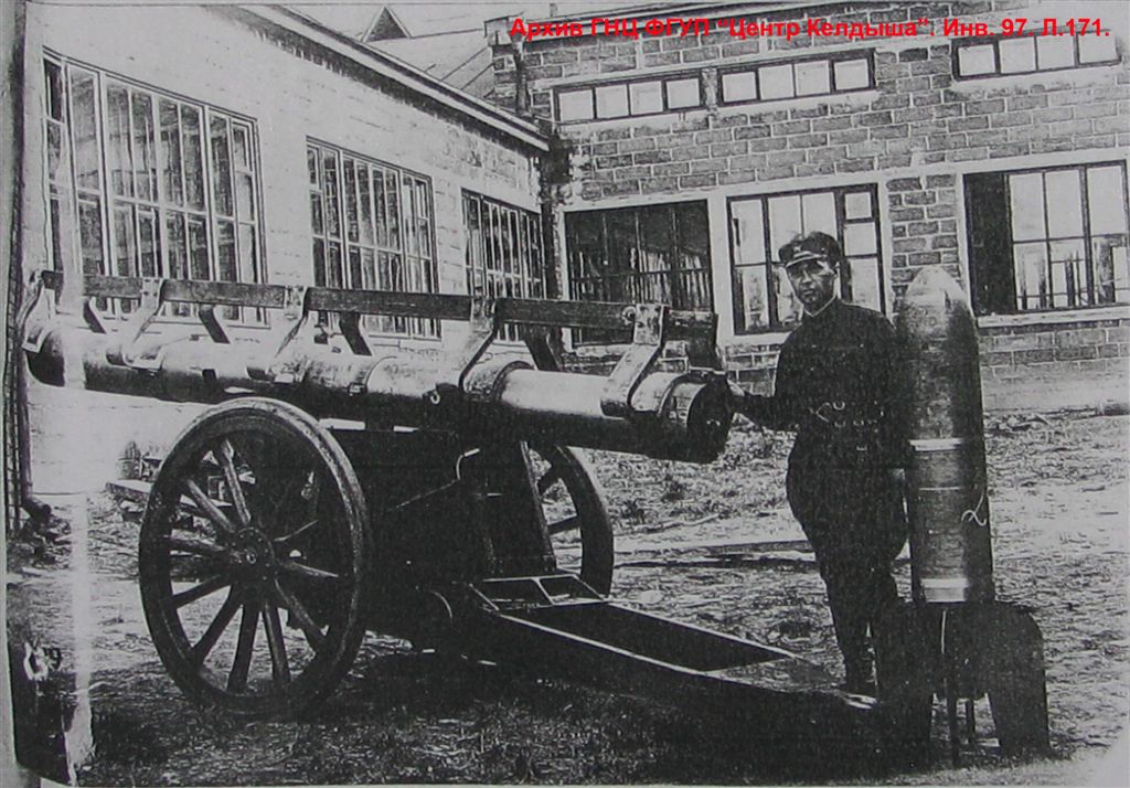
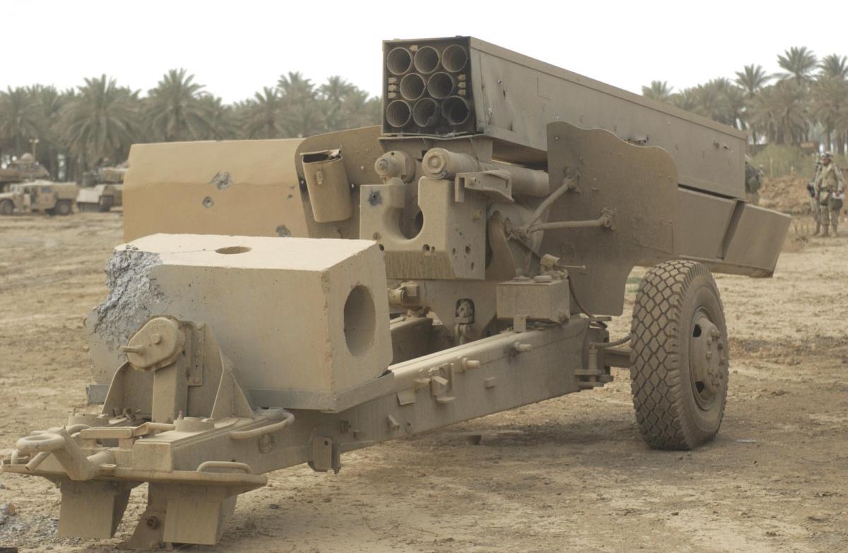
In accordance with the Resolution of the Council of Ministers of the USSR No.144-85ss dated February 4, 1956, according to the tactical and technical requirements of the State Automobile Inspection No.007109 dated February 10, 1956, the MD-24-F high-explosive turbojet long-range projectile was developed into the M-24 jet system. On July 10, 1958 in the military unit 33491 were carried out heap tests of experimental turbojet long-range missiles MD-24F design NII-1. Shots were fired from a single guide mounted on a 152mm howitzer-gun ML-20. It should be noted that as far back as the 30s in the USSR, a rocket launcher (see photo) and a landfill gun (see photo) were created on the basis of artillery guns for the experimental firing of single missiles to launch a 245 mm rocket blast projectile. This technical solution has been used in the future (it is interesting that in Iraq, the U.S. military also found a multiple rocket launcher based on an artillery gun with a transport and launch container from a Brazilian ASTROS MLRS combat vehicle - see photo).
By Decree of the Council of Ministers of the USSR N 426-211 of April 17, 1957, NII-1 GKOT was determined to be the head organization for the development of the "MV-24F" rocket projectile with a direct-flow air jet engine and a range of 30-40 km in the M-24 system, with the deadline for submission of the technical design in the III quarter of 1958. In the course of their work, the specialists encountered a number of difficulties, in particular, the presence of specific vibration combustion in the SARD chamber, special structural strength issues, etc.
At an unspecified time, the MS-24 and MS-24FUD projectiles were designed or developed in the case of poisonous (chemical) substances.
In 1955, the specialists of Plant No. 121 (now JSC "Bryansk Red Banner of Labor Chemical Plant named after the 50th Anniversary of the USSR") develop and submit for export the technical documentation, including the M-24F product.
After the publication of the Service Manual "BM-24 Combat Vehicle (index 8U31)" in 1958, the BM-24 combat vehicle was upgraded in order to increase the strength of mechanisms and its performance in general. The name "BM-24M combat vehicle (index 2B3)" was given to the new model.
In 1957, the Main Artillery Directorate (GAU) was engaged in a pre-design study of the combat vehicle BMD-24B.
During the work on the 122-mm unguided missile to the "Grad" system at the engine test bench without thermal insulation was developed and tested by firing in the volume of 420 launches from the ballistic guide mounted on the BMD-24 combat vehicle.
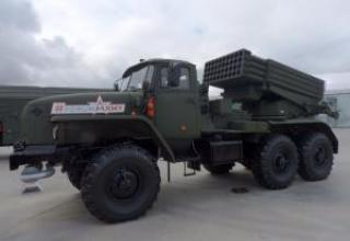
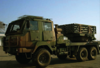
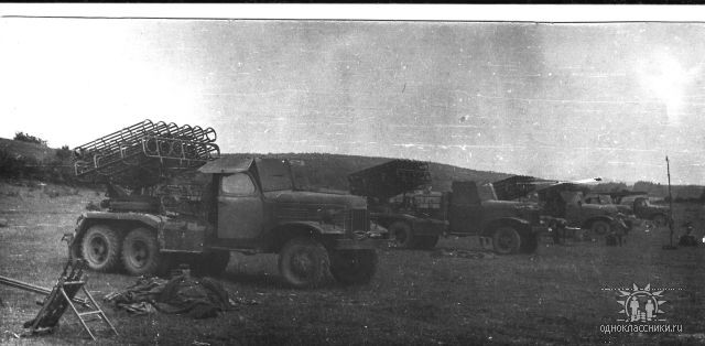
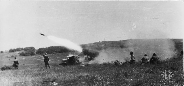
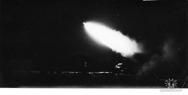
It was in service with the Southern Group of Forces (USSR) in Hungary at least in the second half of the 1960s (photo 1, photo 2, photo 3).
Composition:
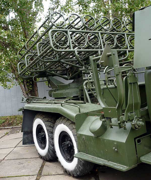
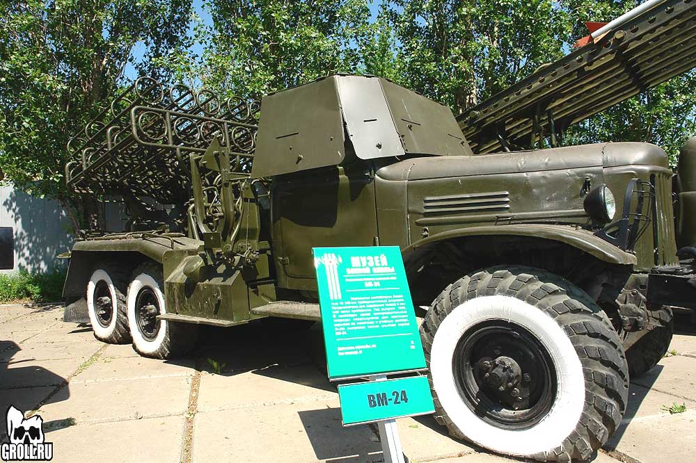
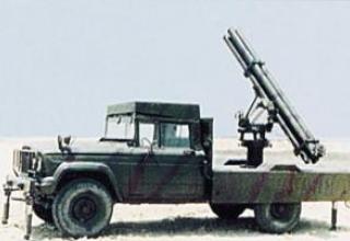
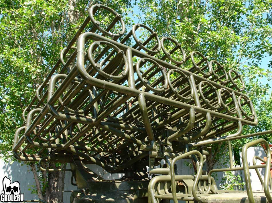
The BM-24 combat vehicle is designed according to the classic scheme with the placement of artillery on the rear of the modified chassis of the truck ZIS-151. The BM-24 artillery unit includes a package of 12 rails, a farm, turning frame, bollard, underframe, lifting, turning and balancing mechanisms, electrical equipment, sighting devices and special chassis equipment. The package of frame (honeycomb) type guides is made of tubular elements, each guide - four longitudinal tubes fastened with four bends - form a lightweight spatial structure, inside which the missile is placed. Each guide is fitted with a contact lever, two locking mechanisms that hold the missile in a hike position from moving forward and backwards. The guides are located on a farm in two rows (see diagram). Only guides Nos. 9 and 2, 11 and 4 are parallel to each other in each row; the remaining guides are arranged so that they form a convergent fan, i.e. guides Nos. 5 and 7, 6 and 8 are arranged at four angles with respect to the middle guides, while guides Nos. 1 and 3, 10 and 12 are arranged at seven angles. This design solution (arrangement of the guideways by a convergent fan) reduced the lateral dispersion of the projectiles. The farm with its 12 guides is designed as a spatial welded structure and together with them forms a swinging part (see photo). It should be noted that the idea of using ramified guides was realized in the design of the machine proposed by Kleigels at the end of the first half of the 19th century (see diagram and description).
The swivelling frame with swivelling part, swivelling, lifting and balancing mechanisms, sighting devices is a rotating part of the launcher. The swivel frame, under the action of the swiveling mechanism, rotates on a pedestal, which is supported by three vertical rollers. Six horizontal rollers centre the rotation of the swivel frame and keep it from tipping over on the bollard. The bollard is rigidly attached to the underframe, the underframe is in turn attached to the lanterns on the car's axle.
The swiveling mechanism of the worm type, serves for horizontal guidance of guides within ±70° from the longitudinal axis of the combat vehicle. The screw type lifting mechanism is used to give the guides elevation angles. By means of the lifting mechanism, the guides may give elevation angles of +10° to +50° in the sector of horizontal firing of ±70° and 0° to 50° in the sectors of horizontal firing, 25° from the right and left sides. Lift and turn actuators are manual. A spring-loaded, pusher-type counterbalancing mechanism serves to reduce the force on the lifting gear drive handle.
Electrical equipment serves for ignition of powder charge of a projectile; it consists of two storage batteries, a switch, a connecting box, wires, contacts of folding levers and a remote coil. Electric current from the accumulator batteries flows to a switch located in the combat vehicle cab and from there, through the wires (one by one) to the contacts of the flip-lever guides. From the flip-lever contact, current is applied to the projectile candle contact, which ignites a powder charge in the projectile and fires.
Special equipment of the BM chassis consists of protection of the cabin, protection of gas tanks and gas tank, jacks, intercom, seat with a support rack, fenders and a bracket for fire extinguisher. Cabin protection protects the cabin and the calculation located in it from the gas jet of projectile at gunshot, and the protection of gas tanks and gas tank protects the gas tanks and gas tank from mechanical damage.
Two jacks located at the rear of the combat vehicle were lowered to the ground when the gun was fired. The jacks are needed to unload the rear axle springs and ensure the vehicle stability when firing. Firing from the combat vehicle can be conducted either from the shelter by means of a remote reel (up to 80 m from the combat vehicle) or directly from the BM cab.
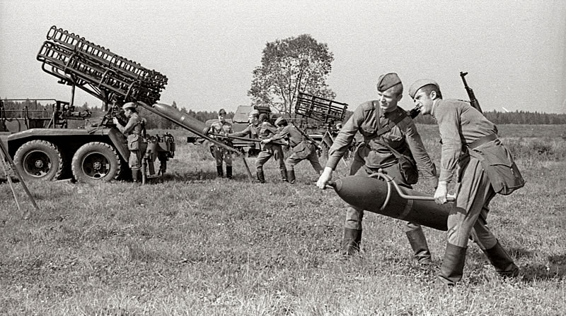
The fighting vehicle was charged manually using a special grip and a tray. Two numbers of calculation lifted the projectile with the grip, and the third supported the projectile behind the nozzle bottom. Then the projectile was placed on the tray and sent to the guide rail until the projectile reached the rear lock (see photo1, photo2).
For firing from the BM-24 combat vehicle, the 240 mm M-24F and M-24FUD turbojet shells with extended range (see description), as well as the MS-24 projectiles with poisonous substance, were used. In 1962, the MD-24F (see description) and MS-24UD turbojet projectiles with extended range (17500m and 16000m, respectively) were adopted for service. The head part of the 3X1 MS-24 projectile was equipped with 19 kg of P-35 substance. The MS-24UD had a longer range, but contained less poisonous substance (12 kg).
The combat vehicle with the gun count, loaded with twelve shells, is able to march without refueling up to 600 km and can open volley fire in 1.5-2 minutes after the command "To battle". The fighting vehicle can be fired at a high rate of fire: the first 12 shells can be fired in 6-8 seconds, and every next 12 shells - in 3-4 minutes.
Upgrade
The artillery unit of the upgraded BM-24M combat vehicle (index 2B3) was mounted on the modified chassis of the ZIL-157 truck.
In particular, changes were made to the mounting and fixing of rails on the farm of the artillery unit. Fastening of each guide was provided with 4 bolts with spring washers (the clamping by electric welding was canceled).
A worm gear instead of a worm gear was installed in the bollard chase.
In the underframe design, the front transverse channel was extended to attach sheets of rear right and left fuel tanks to it.
A worm with a bronze shirt was introduced instead of a steel worm in the swivel mechanism design. The number of windings of the worm was reduced from 15 to 7.
Some structural changes were introduced in special chassis equipment, as the chassis of the ZIL-157 truck differed from the ZIL-151 truck chassis. The front part of the seat (for four calculation numbers) was made folding.
The combat vehicle BM-24M (index 2B3) was equipped with a panorama PG-1 with a gun collimator K-1.
Characteristics:
| Structural data | |
| Caliber, mm | 240,6 |
| Number of guides | 12 |
| Guide length,mm | 2000 |
| Largest elevation angle, hail. | 50 |
| Smallest elevation angle, hail. | 0 |
| Angles of horizontal guidance, hail: - At elevation angles from 0 to +10° (in horizontal firing sectors from ± 45° to ± 70°) - at elevation angles from +10 to +50° |
25 ±70 |
| Panorama eyepiece height, mm | 1475 |
| Dimensional data | |
| Length in hiking position, mm | 6930 |
| Width in hiking position, mm | 2320 |
| Width in combat position, mm | 2650 |
| Height in hiking position, mm | 2800 |
| Height at highest elevation angle, mm | 3510 |
| Weight data | |
| Weight of the loaded fighting vehicle with the calculation of 8 persons, kg | 8910 |
| Weight of combat vehicle in camping position without calculation, kg | 7110 |
| Weight of combat vehicle with shells, kg | 8910 |
| Weight of the artillery unit, kg | 1420 |
| Guide weight, kg | 30,5 |
| Farm weight, kg | 205 |
| Swing frame weight, kg | 280 |
| Weight of the worm gear cabinet, kg | 200 |
| Lifting weight, kg | 60 |
| Weight of balancing mechanism, kg | 40 |
| Operational data | |
| The minimum time required to produce a full salvo, sec | 6—8 |
| Time of transition from marching position to combat without recharging, mines | 1,5-2 |
| The time it takes to charge a combat vehicle, mines. | 3—4 |
| Lifting gear drive handle force, kg | up to 10 |
| Force on swing drive wheel, kg | up to 8 |
| Change of elevation angle in one revolution of the lifting gear drive flywheel | 0°40' |
| Changing the swing angle in one revolution of the swing drive handwheel | 1°40' |
| Maximum speed of a loaded fighting vehicle on paved highway, km/h. | 60 |
| Highest ford depth with hard bottom overloaded by loaded combat vehicle, mm | 750 |
| The greatest lift over a loaded combat vehicle in dry and hard ground, hail | 28 |
Testing:
As of 01.01.1950, in July 1949 the projectile successfully passed the state tests.
At the time of drawing up the document at the factories of gross production was producing a batch of shells for military tests.
According to data from 1977, the specialists of the Israel Military Industries (Israel Military Industries) developed a 240 mm projectile designed to fire a 12-charged war machine (launcher).
The body of the combat vehicle (combat unit) was manufactured by forging method with high precision machining. When the combat unit is torn, about 1,200 steel fragments with a 12,000-square-metre chima killer will break off. When 12 rounds are fired in volley at a range of 10,000 square metres, an area of 125,000 square metres is hit. A circular variation of 0.8% of the range is possible.
The turbojet projectile can be equipped with an instant or slow motion fuse (0.5 second deceleration). A non-contact fuse may be fitted if required.
The engine is designed with 16 nozzles (nozzle openings), after which the combustion products are allowed to rotate to stabilize the projectile. It also includes seven solid fuel draughts and an electric ignition mechanism. The pressure in the combustion chamber is 150 atm; the traction force is 4000 kg, the combustion time is 1.2 s and the total impulse is 4800 kg/s.
Main characteristics of the projectile
| Length | 1290 mm |
| Weight, kg: | |
| shell | |
| full | 110,5 |
| after a fuel burnout | 85,8 |
| combat unit | 30 |
| BB (TNT) | 18,3 |
| fuels | 24 |
| Firing range, m (at an elevation angle of 45°) | 10 700 |
| Shot rate, m/s. | |
| initial | 40 |
| at the end of a fuel burn | 400 |
| when faced with an obstacle | 270 |
For storage and transportation, the projectile is placed in a polystyrene container, the fuses are placed in wooden containers.
Sources:
- Архив ВИМАИВиВС. Журнал Артиллерийского Отделения Военно-Ученого Комитета от 20 июня 1847 года. Ф. ВУК, арт. отд. Г. 1847-1849. Оп. 40, Д. 105. Л. 3-4,8-10.
- Архив ГНЦ ФГУП “Центр Келдыша”. Инв. 97. Л .167,171.
- Боевая машина БМ-24 (индекс 8У31).Руководство службы. Военное издательство МО СССР, 1958
- Боевая машина БМ-24. Руководство службы. – М.: Воениздат, 1985, - С. 201.
- Волосухин В.М. Боевые ракеты СССР. 1941-2003 гг. – Новосибирск. СибАГС, 2004. – С. 394.
- Дополнение к Руководству службы “Боевая машина БМ-24 (индекс 8У31) изд. 1958г. Боевая машина БМ-24М (индекс 2Б3)”. – М.: Воениздат, 1961. – С. 3,5,10,40.
- Краткая история СКБ-ГСКБ Спецмаш-КБОМ. 1 книга. Создание ракетного вооружения тактического назначения 1941-1956 гг. – М.: Конструкторское бюро общего машиностроения, 1967. – С. 67.
- Носовицкий Г.Е. Продолжение “Катюши”. М.: Вузовская книга, 2005. – С. 14,373-375,394.
- РГАЭ. Ф. 298. Оп. 1. Д. 1612. Л. 41.
- Сагайдако В.В. Развитие завода в 1946-1960-х гг. // ОЧЕРКИ ИСТОРИИ АРТИЛЛЕРИИ ГОСУДАРСТВА РОССИЙСКОГО. Сухопутная артиллерия (под редакцией Начальника ГРАУ Минобороны России генерал-лейтенанта Н.М.Паршина). Составитель М.А.Первов – М.: Столичная энциклопедия, 2017. – С. 542,543.
- С П Р А В К А О состоянии на 1.1.1950 г. отработки опытных образцов реактивного вооружения согласно Постановлений Совета Министров СССР № 1175-440сс от 14.1У.48 г. и № 5766-2166 от 27.XII.49 г. / Реактивный пороховой снаряд фугасного действия М-31А. Завизированный документ. Подписи С.Бодрова нет. 10.01.1950 г. // РГАЭ. Ф. 334. Оп. 1. Д. 163. Л. 1,4.
- ОБ'ЯСНИТЕЛЬНАЯ ЗАПИСКА по опытно-конструкторским и научно-исследовательским работам, выдвигаемым в проект плана по наземному реактивному вооружению на 1953 г. ЗАМЕСТИТЕЛЯ НАЧАЛЬНИКА ГАУ генерал-майора инж.техн.службы А.СОКОЛОВА от 11 декабря 1952 года. Подлинник. 10.12.52 г. // ЦАМО РФ. Ф. 81. Оп. 175255сс. Д. 91. Л. 77,78,78об.
- ЦАМО РФ. Ф. 81. Оп. 160821сс. Д. 124. Л. 10-19об.
- ЦАМО РФ. Ф. 81. Оп. 173178сс. Д. 430. Л. 1,10,19.
- ЦАМО РФ. Ф. 81. Оп. 173178сс. Д. 431. Л. 5-7.
- ЦАМО РФ. Ф. 81. Оп. 175255сс. Д. 68. Л. 57-58.
- ЦАМО РФ. Ф. 81. Оп. 836698сс. Д. 222. Л. 13-15,129,132,134,141.
- ЦАМО РФ. Ф. 81. Оп. 856348сс. Д. 41. Л. 28,29,67.
- URL: http://kr.blog.yahoo.com/shinecommerce/folder/58.html?m=lc&p=11&tc=107&tt=1267631615&pc=5
- URL: http://www.oborona.ru/includes/periodics/maintheme/2016/0428/174918261/detail.shtml
- URL: http://news.rambler.ru/22580021/
- URL: http://www.russianarms.ru
- URL: http://477768.livejournal.com/4305617.html
- Falaq rocket system detailed. // Jane's Defence Weekly. – Vol.39. – 15 January 2003. – №2. – P. 14.
- Forecast International. – August 2001.
- Jane’s Armour and Artillery 1986-1987. – London: Jane’s Publishing Limited, 1988. – P. 750-751,764.
- The World Defence Almanac 2000-2001. – P. 264.
- The World Defence Almanac 2003-2004. – P. 247.
- Таблицы стрельбы фугасными турбореактивными снарядами М-24ФУД (окрашенными). Индекс снаряда Ф-961У (Боевые машины БМ-24, БМ-24Т). Издание второе. Воениздат, М.: 1959. – С. 141.
- Разработка в Израиле 240-мм реактивного снаряда для многоствольной пусковой установки // Зарубежная военная техника. Серия II. Техника и вооружение сухопутных войск. Выпуск 8. Август 1977. С. 10-11.
