The development of the combat vehicle BM-24T was introduced in the development plan for 1951. 4 by the Administration of GAU and approved by the Resolution of the Council of Ministers of the Union of SSR № 4814-2095ss of 04.12.50. In accordance with this Resolution, it was envisaged that the State Union Design Bureau of the Ministry of Machine Building and Instrumentation /MMIP GSCB, Chief Designer Barmin V.P./ should have developed and submitted for factory testing in the 4th quarter of 1951 two prototypes of the BM-24T combat vehicle based on the AT-S medium artillery tractor.
To carry out this work, by Order No.719799 of the Deputy Military Minister of the USSR, dated 25.06.51, the Head of the State Automobile Warfare Directorate was obliged to allocate two medium artillery tractors AT-S to the SSCB MMIP in the III quarter of 1951. But the tractors were not singled out in 1951 because of the delay in their production by the Kirov plant /Chelyabinsk/. Delay in the delivery of tractors caused a delay of about a year in the development of BM-24T.
To carry out the works, the Tactical and Technical Requirements (TTT) No. 005764 for the BM-24T fighting vehicle based on the AT-S medium-duty artillery tractor were prepared and approved by the Soviet Army Artillery Commander Kazakov V.I. During the development, they were specified (see the electronic version of the document).
During the development of TTT No. 005764, the design of the medium artillery tractor AT-C, in particular the dimensions of the cab, had not yet been finally determined. Paragraph 6 of these TTTs provided for a minimum elevation angle of 14° and a maximum elevation angle of 70° when firing through the cab. When firing from the side, it was from 0° to +70°.
For the installation of prototype combat vehicles MMiP received one AT-C tractor with a large cabin, and the second tractor - without a cabin. When considering the sketch design, it turned out that it would be possible to mount the launcher on the tractor with the cab, providing the elevation angles stipulated in paragraph 6 of the TTT, but at the same time, the centre of gravity of the launcher would be located high, which would have a negative impact on the operational qualities in terms of stability, strength and convenience of servicing the combat vehicle.
In order to enable the development of the most rational design of the BM-24T, taking into account all the features of the running gear, paragraph 6 of TTT No. 005764 has been adjusted. The angles of vertical firing were taken from +20° to +60° when firing through the cabin, and from 0° to 60° when firing from the side.
During the design process of the BM-24T, it became advisable to use a special trailer /charging box/ to transport a set of shells towed by the same combat vehicle. See the TTT to the trailer.
The following requirements have been formulated for the trailer:
- The trailer must carry 24 or 36 shells weighing 113 kg without capping. The total weight of the trailer with the load shall not exceed 8 tons.
- The design of the trailer shall ensure the convenience of stowage and removal of the shells, as well as their securing against displacement when the trailer is moving on roads of different quality and in off-road conditions.
- The track width of the trailer shall correspond to the track width of the AT-C tractor.
- The trailer shall be sprung, have wheels with 2K tyres and meet the requirements for its use in off-road conditions when towing with the AT-C tractor.
- The trailer shall be connected to the trailer attachment device of the AT-C towing vehicle through a drawbar ensuring the flexibility of the connection allowing the trailer to be tilted in the longitudinal and transverse directions set for the BM-24T combat vehicle. Adjustment of a trailer shall be easy and quick and shall not allow its spontaneous detachment under any operating conditions.
- The angle of transverse stability /side roll/ for the trailer shall be not less than the angle specified for BM-24T combat vehicle.
- Clearance of at least 0.4 m.
- The trailer must have a brake that allows the wheels to brake both when driving downhill and when uncoupled.
- The trailer shall have reflective light signals from the rear and sides, and, in addition, an electric stop light signal with electric power supply from the AT-C tractor.
- When transported by rail, the trailer shall fit into the railway dimension "O".
- The trailer shall have 2 spare wheels and devices for its reliable fixation.
- The design of the trailer shall be developed taking into account the possibility of its long-term storage in warehouse conditions without violation of service properties.
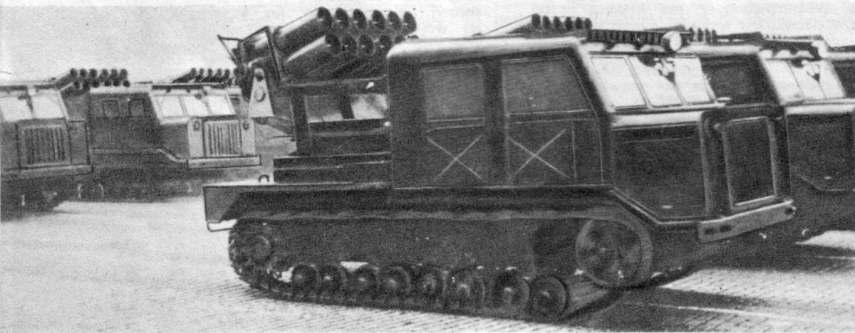
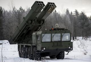
The BM-24T combat vehicle was adopted for service with the Soviet Army in 1956.
Composition:
The BM-24T was designed to fire 240 mm M-24F and M-24FUD turbojet shells. It was used for:
- The suppression and destruction of strongholds and resistance units at the front line and in the depth of the enemy's defense;
- the destruction of settlements that have been turned into enemy resistance nodes;
- the destruction and suppression of enemy artillery and mortar batteries;
- repelling massive tank attacks by the enemy;
- repelling enemy infantry attacks.
When fired from a BM-24T combat vehicle, the projectiles flew closer and to the right than the same projectiles fired from a BM-24 combat vehicle. This information allows us to conclude that the type of guide affects the flight of the projectile.
Due to its high cross-country capability, the BM-24T Vehicle could operate as part of the tank forces in conditions of complete off-road capability. The combat vehicle, loaded with twelve shells, could march without additional fuel for a distance of up to 300 km. The high maneuverability of the BM-24T combat vehicles made it possible to concentrate a large number of combat vehicles in the required area in a short period of time and suddenly open fire.
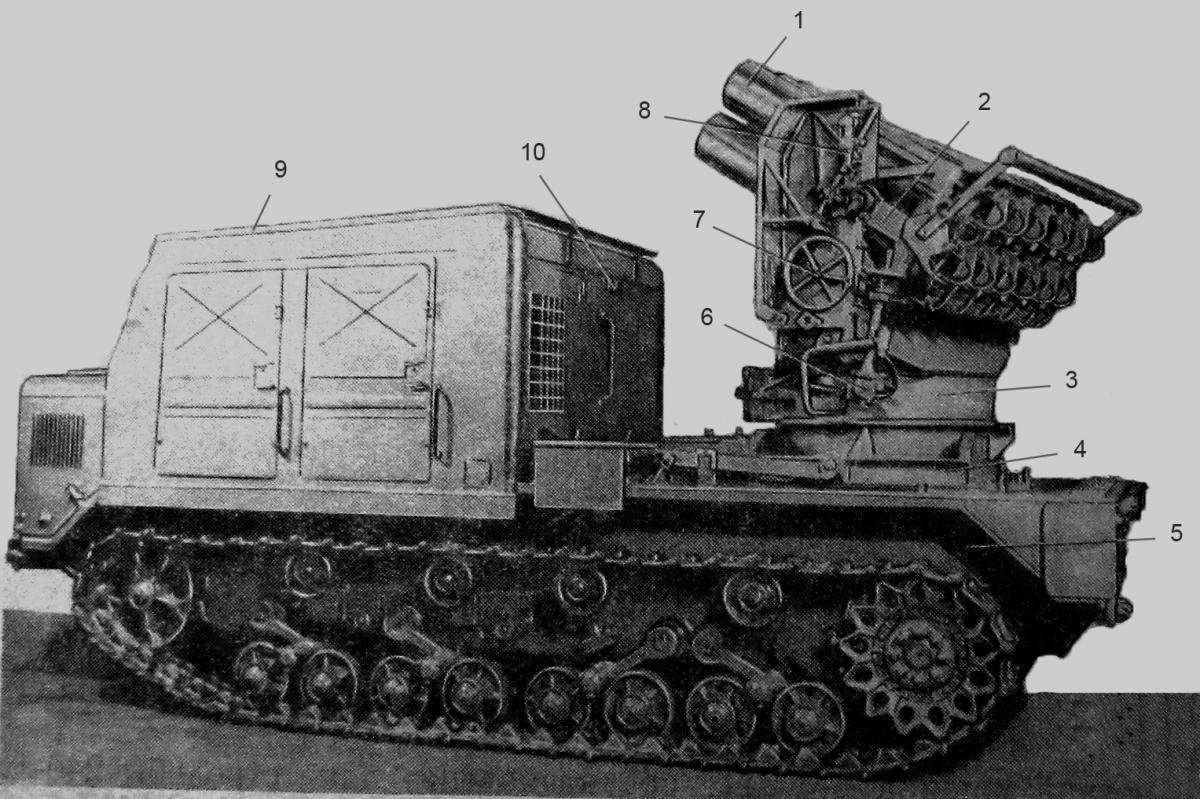
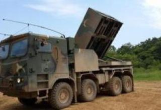
Fighting vehicle BM-24T:
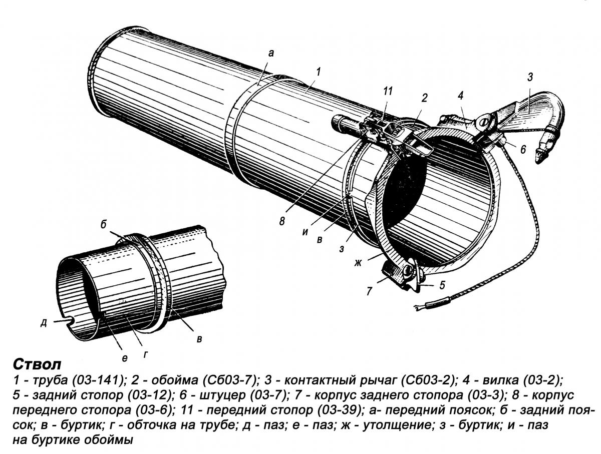
- 1 - barrel;
- 2 - the farm;
- 3 - swivel;
- 4 - bollard;
- 5 - frame;
- 6 - swivel mechanism;
- 7 - lifting mechanism;
- 8 - sighting devices;
- 9 - cabin protection;
- 10 - light alarm system.
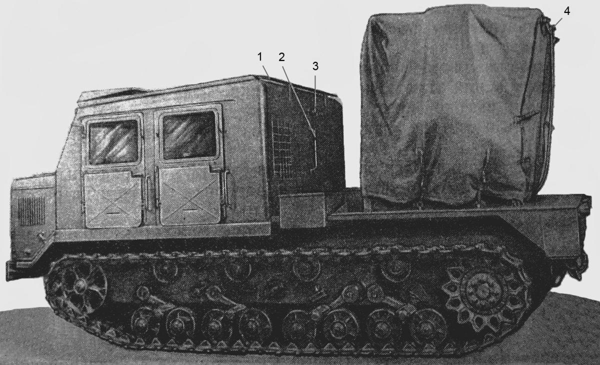
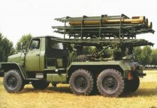
Fighting vehicle BM-24T (hike position under the cover):
- 1 - handrail;
- 2 - a bracket;
- 3 - alarm unit;
- 4 - rear alarm unit.
BM-24T consisted of artillery and running gear.
The artillery unit consisted of twelve barrels, a farm, swivel, bollards, frame, swivel and lifting gear, electrical equipment, sights and special chassis equipment.
The undercarriage was the middle AT-C artillery tractor with removed body. The body was replaced by a welded frame on which all the components of the combat vehicle's artillery unit were mounted and fixed.
Barrel 1 (see diagram) was intended to guide the projectile flight when fired. The barrels were mounted on the farm in two rows parallel to each other, 6 pieces in each row.
Farm 2 was intended to mount the barrels. It was a spatial welded structure of channels, corners, front and rear plates with holes in which the barrels were inserted. It was mounted with two pins in the swivel bearings, where it could rotate in the vertical plane, and together with the barrels and sighting equipment mounted on it was a swinging part of the combat vehicle.
Swivel 3 was designed to mount the swivel part, lifting and rotating mechanisms. The swivel was connected to the bollard by means of a ball epaulet and could rotate horizontally. Bollard 4 served as a base for swivelling swivel with swinging part and swivelling with it in the horizontal plane of combat vehicle parts. The bollard was fixed to the spars of the frame.
Frame 5 served as a base for mounting all the components of the combat vehicle artillery unit. The frame was a spatial welded structure and was installed and fixed to the tractor's frame. The pivoting mechanism 6 served for horizontal guidance of the barrels within ±90° from the longitudinal axis of the combat vehicle. The pivoting mechanism consisted of a spur gear, mounted on a bollard, gearbox and drive unit, mounted on a swivel.
The bollard, swivel and swivel mechanism constituted the swivel unit.
Lifting mechanism 7 was used for vertical barrel guidance. The barrels could be raised from 0 to 50°, except in the horizontal sector ±68°30' from the longitudinal axis of the war machine, where raising angles were provided from +14°30' to +50°. The minimum angles of elevation when firing through the cab (in sector ± 68°30') were limited by a special locking device.
Electrical equipment was used to ignite the powder charge of the projectile and consisted of an electric current source, a switch, a remote coil, a junction box, manifolds, a switch and wiring.
The source of electric current for electrical equipment was one battery of AT-C tractor type 6STEN-140M with voltage of 12V. Electric current was supplied from the accumulator battery to the switch P-3, installed in the cab of the combat vehicle, and from it through the electric cables alternately to the contacts of contact levers of the barrels. From the contact lever current was applied to the projectile candle contact, resulting in the ignition of the projectile powder charge (gunshot).
Sighting devices 8 served to guide the war machine. They included: sight, panorama, gun collimator and insert. When firing at night, the sight and panorama were illuminated by light bulbs with directional light.
On each combat vehicle there were milestones for hanging the main firing direction and a hanger for mutual marking of combat vehicles when building a parallel fan.
To measure ground wind speed and direction, every four combat vehicles were equipped with a field wind turbine.
Special equipment of the running gear of the combat vehicle consisted of a 9-cab protection, 10 light alarms and an intercom system. Cab protection protected the cab from the gas jet of projectile when fired. The three-colour light alarm system served as a link between the combat vehicles on the march. The intercom was used for internal communication between the commander of the combat vehicle, the driver, one of the calculation numbers and the signaler behind the cab.
To protect against dirt, dust and rain, the artillery part of the combat vehicle was covered with a tarpaulin cover. The sight was also covered with a tarpaulin cover. Calculation of the combat vehicle was located in the cab, and one of the numbers of the calculation (signaler) was behind the cab.
Characteristics:
| Main tactical and technical data of BM-24T | |
| Structural data | |
| The diameter of the barrel channel, mm | 241 |
| Shaft number | 12 |
| Trunk length, mm | 1400 |
| The highest elevation angle, º | 50 |
| Angle of horizontal guidance, º | ±90 |
| Smallest elevation angle, º: | |
| in the horizontal guidance sector ± 68º30' from the longitudinal axis of the PM | 14º30' |
| in horizontal guidance sectors from 68º30' to 90º from each side | 0º |
| Dimensions (in hiking position) | |
| Length, mm | 5970 |
| Width, mm | 2435 |
| Height, mm | 3000 |
| Weight data | |
| Weight of LM with calculation, shells and a set of ZIP, kg | 16100 |
| Weight of LM without shells and calculation, kg | 14118 |
| Weight of the artillery unit, kg | 2870 |
| Weight of the oscillating part, kg | 881 |
| Weight of the artillery pieces, kg | 233 |
| Operational data | |
| Maximum time required to produce full salvo, sec. | 6-8 |
| Time to move from camping to combat without recharging, min. | 1,5-2 |
| Time required to charge, min. | 3-4 |
| Lifting gear drive flywheel force, kg | up to 10 |
| Force on the handle of the swing drive flywheel, kg | up to 10 |
| Change of elevation angle in one revolution of the lifting gear drive flywheel, º | 1 |
| Changing the swing angle in one turn of the swing drive wheel, | 1º52' |
| Maximum speed of a charged PM on medium quality dirt roads, km/h. | 35 |
| Maximum pulling force of the winch, kg | 15000 |
| The deepest ford, m | 1 |
| Maximum lifting angle, º | 30 |
| Maximum roll angle, º | 25 |
| Maximum turning radius, m | 3,5 |
Testing:
The first launches of K-10 in marine aviation were made by North Sea crews on the Caspian Sea in July 1960. Having departed from the airfield of the 33rd Center near Nikolaev, a pair of Tu-16K-10s reached the target, and from a height of 10,000 m at a range of 175 km the crew of Colonel Myznikov made the launch. Due to a pointing error, the missile did not reach the target, having fallen into the sea at 40 km, the crew of Lieutenant Colonel Kovalev, who followed, attacked from a distance of 170 km, achieving a direct fall into the target - the tanker "Chkalov" drowned in shallow water. Within two weeks, three more attacks were carried out, one of which again failed due to operator's error, and in one missile hit the crest of the wave just 200 m from the ship.
The training and combat launches were accompanied by supervision of industry representatives - nevertheless, the system was accepted with many reservations and required prompt correction of defects. For this purpose, even a special design and technological bureau (SCTB) was organized with participation of engineers from MAP, Design Bureau, Research Institute and AUMF. The researches carried out on the basis of the 33rd Center showed the practical feasibility of target detection from 450 km by adjusting the frequencies and length of the radar pulses. It was possible to launch long-range missiles from 325 km, and the lower limit of the aircraft flight was 500-600 m. The radar antenna of the carrier carried out scanning, mechanically rotating through the azimuth of 120 °, making it possible to turn away from the target after launch and continue to provide escort. Usually, the turn-off was performed at the 100th second with a roll of 9-12°, dictated by the possibility of stabilization of the antenna. Approximation to the target, depending on the flight mode and altitude of the launch, did not exceed 140-160 km (later withdrawal from the attack at the start of K-10SD from the maximum range could be carried out at a distance of 265 km).
In one of the departures for tactical launch in 1961, the crew of Captain G.A.Zimin faced an emergency situation, when the missile released into the starting position could not be returned. Nothing good landed with a hanging missile did not promise, because with a normal landing angle of 8 °, there was a great risk of "combing" the missile on the ground. Nevertheless, the crew managed to get the plane to land successfully, and then the instructions for such a case were introduced in the pilot's instructions.
In 1960-62, the K-10 missile system was equipped with seven air regiments of all Soviet fleets: 2nd MRAD of the Black Sea, 5th MRAD of the North, 25th and 143rd MRAD of the Pacific and 57th MRAD of the Red Banner Baltic Fleet. The intensity of development and combat training of maritime aviation crews looked impressive: for the first six months of operation in 1960 there were 79 launches, the next - 126, and in 1962 - 147 (however, the reverse side was a large consumption of combat missiles, and a duplicate aircraft like "Kometa", which allows you to save money and expensive products, for the K-10 was not available).
Another shortcoming was revealed - poor preparedness of ground services for operation of complex equipment. At first, it was assigned to a special engineering and aviation service of SIS, and the issues of warehousing, engaged in repair and maintenance base. Getting rid of duplication of work, the structure was reorganized and introduced a division of responsibilities: all systems of the aircraft were serviced by IAS specialists regiment, and the full list of work on missiles was carried out by the maintenance base.
The measures taken allowed reducing the time of equipment preparation and improving the quality of work. The confirmation was the reduction of the number of unsuccessful launches due to mistakes in the preparation of the mattress - already in 1962, their number decreased by 20%. Near the aircraft were equipped with shelters, where there were refueled and equipped with missiles, pre-tested and flying in the air on "its" carrier. The procedure of suspension and preparation of K-10 was reduced to 45 minutes, and this work was fully carried out by regimental technicians and crews - preparation for the departure of two squadrons with 16 Tu-16K-10 reduced in time by half.
We managed to reduce the number of failures, although the number of complaints about the shortcomings and defects of the system remained tangible, so the reliability of the Tu-16K-10 was inferior to other, simpler complexes, primarily through the fault of the equipment. In 1961, almost half of the completed launches failed, and about a third - due to design and manufacturing flaws.
Face-to-face with Soviet missile carriers, the United NATO Fleet had to meet in September 1964 during a major exercise "Tim Work-64", covering the entire North Atlantic. More than half a dozen ships, including two aircraft carrier groups, participated. The squadron was discovered by Tu-95 reconnaissance aircraft of the Northern Fleet, after which the command of the 5th MRAD offered to organize a response exercise with the use of aviation "on real targets", showing, for example, the head of the country to the Americans "Kuzkinu mother". Command of the Navy, however, was afraid of bringing the situation to the brink of unleashing a real war, but the top leadership of the country gave the conceived "good".
By order of the Air Force Headquarters of the NF plan was adopted for implementation. In the evening of September 21, three squadrons of Tu-16K-10 strike team of Lieutenant Colonel KL Timakov, as well as scouts, designators and interference operators who were covering the missile carriers. The ship's group was found in the ocean, the planes at low altitude stealthily reached the border of the attack. The "missile strike" was launched from three directions with a distance of 160-200 km, and the enemy was helpless to repel it.
At TOF in 1964 there was a case of attack K-10S Japanese ship, which was in the restricted zone of the range. Shino-Maru" was held near Cape Tyk, where the crew of Tu-16K-10 from the 169th MRAP worked out a training task. Having refocused, the rocket went exactly on a new "target". The Japanese were lucky - the fuse was set to detonate on the trajectory to save the targets, and the explosion occurred 400 meters from the board. The wreckage damaged the superstructure and the rocket's engine broke through the ship. Among the crew were wounded, which forced the Japanese to go to the nearest Soviet port of Kholmsk for medical care and repair. The incident managed to jam, and the Japanese side believed that the ship was hit by a crashed Soviet fighter, and expressed sympathy for the lost pilot.
During the largest strategic exercise "Ocean", held in April 1970 and covering all the fleets and water areas, the North Sea Tu-16K carried out 6 rocket launches at the range, thrown into reinforcements to them 10 missile carriers with TOF April 20 attacked the target missiles near the Kola Peninsula. Nine Tu-16K-10 of the Pacific 143rd MRAD, supported by five tankers, carried out tactical attacks in the Sea of Japan, using groups of NATO and U.S. ships as targets.
The Baltfleet's Tu-16K-10 was airborne when it intercepted the mutinous SCR "Storozheva," which left the base and headed for the Strait of Irben during the October 1975 holidays. It was supposed that he wanted to go abroad, and to stop this attempt on November 8 and 9 all forces of the fleet and aviation were alerted. Rocket attack in the area with busy shipping, fortunately, did not take place - Tu-16 found the target when the ship has already been bombed and stalled cars, but they accompanied him on the way back to the base.
With the organization of the base of the Soviet fleet in the Vietnamese port of Kamran there was placed 169th gv. SAP, which, in addition to scouts, target designation and anti-submarine aircraft, at the front positions was a squadron of Tu-16K-10-26. They served there from 1982 to 1989.
Sources:
- ЦАМО РФ. Ф. 81. Оп. 175255сс. Д. 68. Л. 2,4,5,7,8,11,12,14,23-26,29,30,31,36-38,41-43.
- ЦАМО РФ. Ф. 81. Оп. 173178сс. Д. 429. Л. 28,29,41-43,49-51,63,64,70,71,78,79,83,84,89-97,100-105.
- Боевая машина БМ-24Т. Руководство службы. Министерство обороны союза ССР. Военное издательство Министерства обороны Союза ССР. - М.:Воениздат. - 1958. - С. 3-6,162,163.
- Носовицкий Г.Е. Продолжение “Катюши”. М.: Вузовская книга, - С. 422.
- Письмо Р/447825сс/25.04.53г. Краткое содержание: о разработке ГСКБ ММ боевой машины БМ-24Т. ЗАМЕСТИТЕЛЮ МИНИСТРА МАШИНОСТРОЕНИЯ СССР товарищу ПАРШИНУ П.И. от ГЕНЕРАЛ-МАЙОРА ИНЖ.ТЕХН..СЛУЖБЫ А.СОКОЛОВА. Копия. 22.04.1953 г. // ЦАМО РФ. Ф. 81. Оп.175255сс. Д. 91. Л. 71,72,72об.
- Таблицы стрельбы фугасными турбореактивными снарядами М-24Ф. Индекс снаряда 53-Ф-961 (Боевые машины БМ-24, БМ-24Т и БМ-24М) ТС-59, ТС-59С, ТС-59Б. Издание второе. Воениздат. – М.: 1969. – С. 5.
