
In the list of contractual works carried out by the Jet Research Institute (RRI) for the Automobile Armoured Personnel Management (ABTU), the final calculation of which was to be carried out in the first quarter of 1936, mentioned the contract № 251618c of January 26, 1935 - a prototype rocket launcher on the BT-5 tank with 10 missiles [41]. Thus, we can consider as proved the fact that the idea of creating a mechanized multi-charger unit in the third decade of the XX century did not appear in the late 30's, as it was argued earlier, but at least at the end of the first half of this period. The confirmation of the fact of the idea of using cars for firing missiles in general was also found in the book "Missiles their device and application", by G.E. Langemak and V.P. Glushko, released in 1935. This book concludes, in particular, with the following: "The main field of application of gunpowder missiles is the armament of light combat vehicles, such as airplanes, small ships, vehicles of all kinds, finally, escort artillery"[42].
In 1938, the staff of Research Institute № 3 by order of the Artillery Department conducted work on the object number 138 - a gun for firing 132 mm chemical shells. It was required to produce non-shot machine tools (pipe type). According to the contract with the Artillery Department it was necessary to design and produce a unit with a bollard and a lifting and turning mechanism. One machine was manufactured, which was then found not to meet the requirements. At the same time in Research Institute No. 3 a mechanized salvo missile launcher was developed, mounted on the modified chassis of truck ZIS-5 with 24 rounds of ammunition. According to other data from the archive of the SSC FSUE "Center Keldysh" (former Research Institute ¹ 3) "were made 2 mechanized units on vehicles. They were factory tested by shooting at Sofrinsky Artpoligon and partial polygon tests at TsV HP R.K.A. with positive results". On the basis of the factory tests it was possible to confirm: PCS flight range (depending on the specific gravity of OM) at an angle of 40 degrees is 6000 - 7000m, Wd = (1/100)X and Wb = (1/70)X, useful volume of OM in the projectile - 6.5 l, metal consumption per 1 liter of OM - 3, 4kg/l, the scatter radius of the explosive ordnance in case of a projectile burst on the ground is 15-20l, the maximum time required to fire the entire vehicle in 24 rounds of 3-4 seconds.
The mechanized missile launcher was designed to provide chemical attack by the chemical missile shells (SOV and NEW) of 132 mm with the capacity of 7 liters. The unit allowed to fire at areas as single shots, and volley in 2 - 3 - 6 - 12 and 24 rounds. "Installations, brought together in the battery 4 - 6 machines, is a very mobile and powerful means of chemical attack at a distance of up to 7 kilometers".
Installation and 132 mm rocket chemical projectile for 7 liters of the poisonous substance have been successfully tested and the adoption of the state was planned in 1939. In the table of practical marksmanship of chemical-rocket projectiles indicated the data of a mechanized automotive unit for a sudden attack by firing chemical, shrapnel, incendiary, illuminating and other missile projectiles. The first variant without the guidance device - the number of shells of one volley - 24, the total weight of the poisonous substance release of one volley - 168 kg, 6 automotive plants replace one hundred and twenty howitzers 152 mm caliber, the recharging rate of the car for 5-10 minutes. 24 shots, number of service personnel - 20-30 people in 6 cars. In artillery systems - 3 Artpolk. II-variant with the control device. The data is not specified.
From December 8, 1938 to February 4, 1939 there were tests of unguided 132 mm caliber rockets and auto-installations. However, the unit was presented to the tests as unfinished and did not stand them: a large number of failures were detected when the projectiles came off due to the imperfection of the corresponding parts of the unit; the charging process of the launcher was inconvenient and time-consuming; the rotating and lifting mechanisms did not provide easy and smooth operation, and the sighting devices - the required accuracy of guidance. Besides, the ZIS-5 truck had limited cross-country ability. (See the gallery Tests of the automobile rocket launcher on the ZIS-5 chassis, design of the Research Institute-3, drawing № 199910 for the launch of 132 mm. missiles. (Time of testing: from 8.12.38 to 4.02.39).
The letter of award for the successful testing in 1939 of a mechanized unit for chemical attack (out. Research Institute № 3 under the number 733c dated May 25, 1939 from the Director of Research Institute № 3 Slonimer to the People's Commissar of Ammunition, Comrade Sergeeva I.P.) indicates the following participants in the work: A.G. Kostikov - Deputy Director for technical part, initiator of the installation; I.I. Gvai - leading designer; A.A. Popov - technician-designer; Isachenkov - mechanic for installation; Yu. - prof. consulted the object; Luzhin V. - V. Luzhin, engineer; L.E. Schwarz, engineer [31].
In 1938 the Institute designed the construction of special chemical motorized command for volley firing of 72 rounds [7].
In a letter dated 14.II.1939, comrade Matveev (V.P.K. of the Committee of Defense under the Supreme Soviet S.S.R.) for the signatures of the Director of Research Institute № 3 Slonimer and Deputy Director of Research Institute № 3 of military engineer I rank Kostikov said: "For ground forces, the experience of chemical mechanized unit to use for:
- The use of fragmentation and blast missiles to create massive fire in squares;
- The use of incendiary, illuminating and propaganda projectiles;
- development of a chemical shell of 203 mm caliber and a mechanized unit providing twice the existing chemical power and range of fire"[40].
In 1939, the Research Institute № 3 developed two versions of experimental units on the modified chassis of truck ZIS-6 for the launch of 24 and 16 unguided rockets of 132 mm caliber. Installation of II sample differed from installation of I sample by longitudinal arrangement of guides.
The set of the mechanized unit /on ZIS-6/ for the launch of chemical and shrapnel-flag shells of 132 mm caliber /MU-132/ consisted of 16 missiles. The firing system provided for the possibility of firing both single shells and a volley of the whole ammunition. The time required to produce a volley of 16 missiles was 3.5 to 6 seconds. The time required to reload the ammo was 2 minutes for a team of 3 people. The weight of the structure with the full 2350 kg ammunition was 80% of the calculated load of the vehicle.
Range tests of these installations were conducted from September 28 to November 9, 1939 on the territory of the Artillery Research Pilot Range (ANIOP, Leningrad) (see photo taken at ANIOP). The results of the test range showed that the installation of the I sample due to technical imperfections can not be allowed to military tests. Installation II of the sample, which also had a number of serious shortcomings, according to the conclusion of the commission members, could be admitted to the military tests after significant constructive changes had been made. The tests showed that when fired, the installation II of the specimen swings and the knockdown of the elevation angle reaches 15"30", which increases the dispersion of the projectiles, and when the lower row of guides is charged, the projectile may strike the structure of the farm. Since late 1939, the focus has been on improving the design and construction of Specimen II and correcting deficiencies identified in polygon tests. In this regard, it is necessary to note the characteristic directions in which the work was carried out. On the one hand, this was a further development of installation II of the specimen in order to eliminate its disadvantages, and on the other hand, the creation of a more advanced installation other than that of installation II of the specimen. In the tactical and technical task to develop a more advanced unit ("modernized unit for the RS" according to the terminology of the documents of those years), signed by Yu.P. Pobedonostsev on December 7, 1940, it was planned: to make constructive improvements to the lift-turn device, increase the angle of horizontal guidance, to simplify the sighting device. It was also planned to increase the length of the guides up to 6000 mm instead of the existing 5000 mm, as well as the possibility of firing uncontrolled rockets of 132 mm and 180 mm caliber. At a meeting of the technical department of the People's Commissariat for Ammunition, it was decided to increase the length of the guides to 7,000 mm. The deadline for delivery of the drawings was set for October 1941. Nevertheless, to carry out various tests in the workshops of Research Institute № 3 in 1940 - 1941 there were made several (in addition to the existing) modernized installations for the RS. The total number varies from one source to another: in some sources - six, in others - seven. In the data of the archive of Research Institute № 3 as of January 10, 1941 there are data on 7 units. (from the document on readiness of object 224 (theme 24 of the superplan, experimental series of auto-installations for shooting RS-132 mm (in number of seven pieces. See the letter of UAS GAU №668059)) On the basis of available documents - in a source [19] it is asserted, that there were eight installations, but at different times. As of February 28, 1941, there were six.
Thematic plan of research and development and design work for 1940 Research Institute № 3 NKB provided for the transfer of the customer - AU RKKA - six units for PC-132mm. In the report on the implementation of pilot orders in production for the month of November 1940 at the Research Institute № 3 NKB indicates that the delivery of the customer's batch of six units by November 1940, the STC were taken 5 pcs., and the military leader - 4 pcs.
In December 1939, Research Institute ¹ 3 was tasked to develop a powerful projectile and a rocket launcher for a short period of time to fulfill the tasks of destroying long-term enemy defenses on the "Mannerheim line". The work of the Institute's team resulted in the development of an optic jet projectile with a range of 2-3 km with a powerful blast head with a ton of explosives and a four-guide launcher on the T-34 tank or on a sledge towed by trucks or tanks. In January 1940 the launcher and the rockets were dispatched to the area of hostilities, but it was soon decided to carry out range tests before using them in hostilities. The projectile launcher was sent to the Leningrad Artillery Research and Testing Range. Soon the war with Finland ended. There was no need for powerful blast shells. Further work on the installation and the shell was stopped[43].
Section 2n of the Research Institute № 3 in 1940 it was proposed to perform work on the following objects:
- Object 213 - Electric installation on VMS for firing of lighting and signal devices. R.S. of 140-165 mm calibers. (Note: for the first time the electric drive for a reactive artillery combat vehicle was used in the design of the BM-21 combat vehicle of the M-21 Field Rocket System).
- Object 214 - Installation on a 2-axle trailer with 16 guides of length l = 6mt. for R.S. 140-165mm calibers. (alteration and adaptation of object 204).
- Object 215 - Electrified installation on VMS-6 with R.S. stock and wide range of aiming angles.
- Object 216 - Charging box for RS on a trailer
- Object 217 - Installation on a 2-axle trailer for firing long-range missiles
- Object 218 - Anti-aircraft moving system for 12 units. P.C. of 140 mm calibre with electric drive
- Object 219 - Anti-aircraft stationary installation for 50-80 R.S. of 140 mm caliber.
- Object 220 - Command installation on ZIS-6 vehicle with electric current generator, aiming and firing control panel
- Object 221 - Universal unit on a 2-axle trailer for possible firing ranges of RS calibers from 82 to 165 mm.
- Object 222 - Mechanized unit for tank escorts
- Object 223 - Introduction of mechanized plants into industry of serial production.
In the letter of the Acting Director of Research Institute № 3, 1st rank military engineer A.G. Kostikov about the possibility to submit to the K.V.S. at the USSR SNK data for the award of the Comrade Stalin Prize, the results of work in the period from 1935 to 1940, indicate the following participants of the work:
- rocket launcher for a sudden, powerful artillery and chemical attack on the enemy with the help of missile shells - Authors according to the application certificate of GBPRI № 3338 9.II.40g (copyright certificate № 3338 of February 19, 1940) Andrey Kostikov, Ivan Gvai, Vasily Abolenkov.
- tactical and technical substantiation of the scheme and design of the auto installation - designers: Pavlenko Alexey Petrovich and Galkovsky Vladimir Nikolaevich.
- development of rocket-shrapnel-flag chemical shells of 132 mm caliber. - Schwarz Leonid Emilyevich, Artemyev Vladimir Andreyevich, Shitov Dmitry Alexandrovich.
The basis for the presentation of the Comrade Stalin Prize was also the decision of the Technical Council of Research Institute № 3 NKB from 26.XII.40. [32],[33].
April 25, 1941 were approved tactical and technical requirements No.1923 to modernize the mechanized plant for firing rockets.
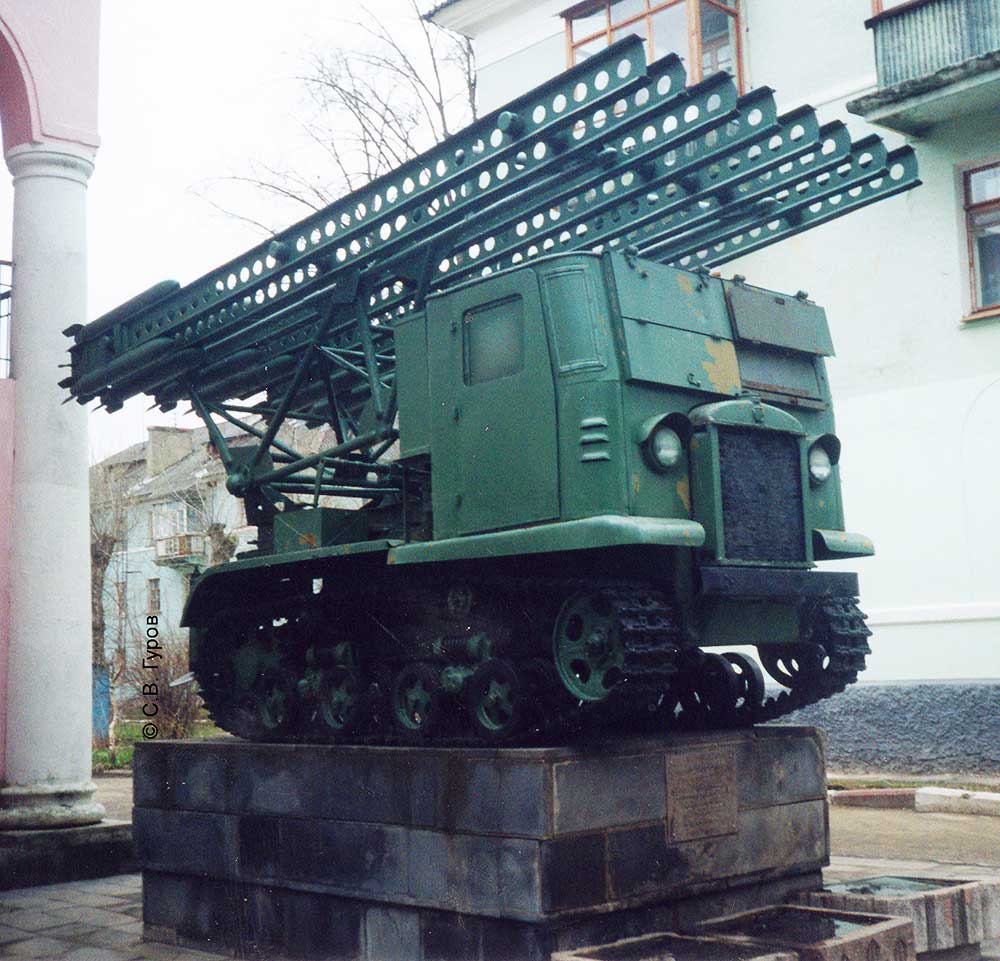
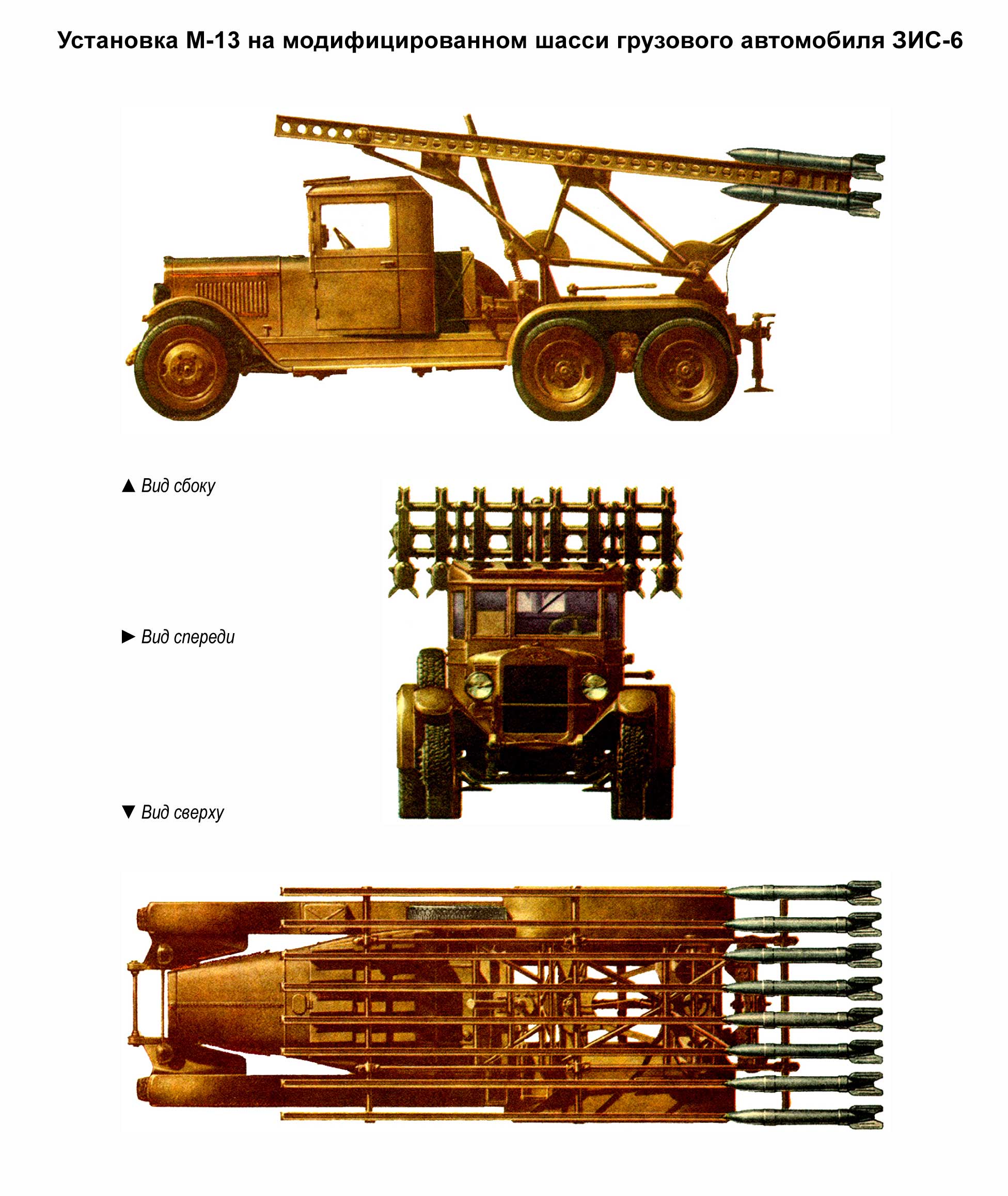
On June 21, 1941 the plant was demonstrated to the leaders of the All-Union Communist Party of Bolsheviks (6) and Soviet government and on the same day, just a few hours before the beginning of the Great Patriotic War, it was decided to urgently deploy the production of M-13 rockets and installations (see scheme 1, scheme 2). The production of M-13 rocket launchers was organized at the Voronezh plant named after M.V. Lenin. Comintern and the Moscow plant "Compressor". The Moscow factory named after Vladimir Ilyich became one of the basic enterprises on release of jet projectiles.
During the war, the production of component units and shells and the transition from serial production to mass production required the creation of a broad structure of cooperation in the country (Moscow, Leningrad, Chelyabinsk, Sverdlovsk (now Ekaterinburg), Nizhny Tagil, Krasnoyarsk, Kolpino, Moore, Kolomna and possibly others). It was necessary to organize a separate military reception of the Guards mortar units. For more information about the production of shells and their elements during the war, please see our gallery website (hereinafter referred to as links below).
According to various sources, the formation of the Guards mortar units began in late July and early August (see:[21]). In the first months of the war the Germans already had data on new Soviet weapons (see: [22]).
The date of acceptance for service of the M-13 machine and shells is not documented. The author of this material established only data on the draft Resolution of the Defense Committee of the USSR SNK of February 1940 (See: [48]). In M.Pervov's book "Stories of Russian rockets" Book One. on page 257 states that "August 30, 1941 the Resolution of the State Defense Committee of BM-13 was adopted by the Red Army. I, S.V. Gurov, got acquainted with the electronic images of the Resolutions of GKO for August 30, 1941 in the Russian State Archive of Social and Political History (RGASPI, Moscow) and found no mention of the data on the adoption of the M-13 in service [49].
In September-October 1941, on the instructions of the General Directorate of Armament of the Guards Mortar Chassis was developed M-13 installation on the modified for mounting the chassis of the tractor STZ-5 NATI. The development was entrusted to the Voronezh plant named after V.I. Makarov. The development was entrusted to Voronezh plant named after Comintern and SKB at Moscow plant "Compressor". SKB performed the development more qualitatively and the prototypes were manufactured and tested in a short time. As a result, the plant was accepted for service and put into mass production.
In December 1941, on the instructions of the Red Army Main Armoured Car Defence Directorate, the SKB developed, inter alia, a 16-charged unit on an armoured railway platform for the defence of Moscow. The unit was a throwing unit of the M-13 serial unit on the modified chassis of the ZIS-6 truck with a modified base. (for more details about other works of this period and the war period in general see: [23] and [24]).
At the technical meeting in SKB on April 21, 1942 it was decided to develop a normalized unit known as M-13N (after the BM-13N war). The purpose of the development was to create the most advanced unit, which would take into account all the changes made earlier in the various modifications of the M-13 unit and to create a throwing unit that could be manufactured and assembled on the stand and assembled on the chassis of vehicles of any brand without much processing of the technical documentation, as it had happened earlier. The goal was achieved by splitting the M-13 unit into separate units. Each unit was considered as an independent product with an index, after which it could be used as a borrowed product in any installation.
During the development of units and parts for the normalized combat unit BM-13H were obtained:
- 20% increase in firing
- to reduce the effort on the handles of the guidance mechanisms by one and a half times;
- doubling the vertical alignment speed;
- increased survivability of the combat unit by armoring the rear wall of the cabin; gas tank and gas pipeline;
- increasing the stability of the installation in a hiking position by introducing a support bracket to disperse the load on the spars of the vehicle;
- increase in operational reliability of the unit (simplification of the support beam, rear axle, etc.;
- significant reduction of welding works, mechanical processing, elimination of bending of the farm rods;
- weight reduction of the unit by 250 kg despite the introduction of armor on the rear wall of the cabin and the gas tank;
- reduction of production time for the unit by assembly of the artillery part separately from the vehicle chassis and installation of the unit on the vehicle chassis by means of fastening clamps, which allowed to eliminate drilling holes in the spars;
- reducing by several times the idle time of the vehicle chassis entering the plant for installation of the installation;
- reduction of the number of fastener sizes from 206 to 96, as well as the number of part names: in the swivel frame - from 56 to 29, in the farm from 43 to 29, in the support frame - from 15 to 4, etc. The use of normalized assemblies and products in the construction of the plant allowed the use of a high-performance flow method for the assembly and installation of the plant.
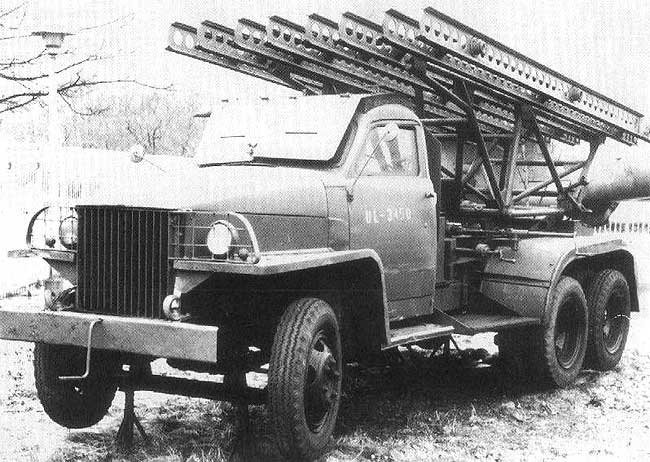
The throwing unit was mounted on the modified chassis of the Studebaker truck (see photo) with 6x6 wheel configuration, which was delivered on a lend-lease. The normalized M-13N was adopted by the Red Army in 1943. The unit became the main model, which was used till the end of the Great Patriotic War. Other types of modified chassis of foreign brands of trucks were also used.
In late 1942, V.V. Aborenkov proposed to add two additional pins to the M-13 projectile in order to launch it from the twin guides. For this purpose, a prototype was made, which was a serial unit M-13, which was replaced by a swing part (guides and the farm). The guide was two steel strips mounted on a rib, each of which had a groove for a drive pin. Each pair of strips was mounted opposite each other with grooves in the vertical plane. The polygon tests carried out did not result in the expected improvement in pile-ups and work was stopped.
In early 1943, SKB specialists carried out work on the development of normalized throwing unit M-13 on the modified chassis of Chevrolet and ZIS-6 trucks. During January - May 1943, a prototype was produced on the modified Chevrolet truck chassis and its testing ground was carried out. The units were adopted by the Red Army. However, due to a sufficient number of chassis of these brands, they did not go into mass production.
In 1944, SKB specialists developed the M-13 on the armored retrofitted ZIS-6 chassis for mounting a throwing unit for launching M-13 shells. For this purpose, the normalized "beam" type guide rails of the M-13N unit were shortened to 2.5 meters and assembled into a package on two spars. The farm was shortened from tubes in the form of a pyramidal frame, tilted down by the top, served mainly as a support for fixing the screw lifting mechanism. Changing the elevation angle of the guide package was made from the cab by means of handwheels and cardan shaft of vertical guidance mechanism. A prototype was made. However, due to the weight of the armor, the front axle and springs of the ZIS-6 were overloaded, as a result of which further work on the installation was stopped.
At the end of 1943 - beginning of 1944, the question of improving the pile rate of fire of 132 mm rounds was raised with the SKB specialists and the developers of the rocket launchers. The designers introduced tangential holes in the diameter of the main working belt to make the projectile rotate. The same solution was used in the design of the M-31 projectile and was proposed for the M-8 projectile. As a result, the heap rate increased, but there was a decrease in the flight range. Compared to the M-13 standard projectile, which had a range of 8470 m, the new projectile with the M-13UK index had a range of 7900 m. Despite this shell was adopted for service with the Red Army.
In the same period specialists of NII-1 (Leading Designer Bessonov V.G.) developed and then tested the shell M-13DD. The projectile had the best index of pile-up, but they couldn't shoot from standard M-13 installations, as the projectile had a rotational motion and when launched from standard rails it destroyed them by detaching the pads. To a lesser extent, this was also the case when launching the M-13UK shells. The M-13DD was adopted for service with the Red Army at the end of the war. Mass production of the shell was not organized.
At the same time, the SKB specialists started search design studies and experimental works to improve the heap rate of firing of M-13 and M-8 rockets through the development of guides. It was based on the new principle of launching the rockets and ensuring their sufficient strength for firing M-13 and M-20 missiles. As giving rotation to the operatives' uncontrollable rockets at the initial section of their flight path improved the idea of giving rotation to the projectiles on the guides without drilling the tangential holes in the projectiles that consume part of the engine power for their rotation and thus reduce the range of their flight was born. This idea led to the creation of spiral guides. The design of the spiral guides took the form of a barrel formed by four spiral rods, of which three are smooth steel tubes and the fourth one is made of a steel square with selected grooves forming an H-section profile. The rods were welded to the feet of the ring cage. In the breech block there was a lock to hold the projectile in the guide and electric contacts. A special tool was created to bend the rods of the spiral guide, which had different lengths of twisting and welding angles of the barrel guides. Initially, the unit had 12 guides rigidly connected into four cassettes (three guides each in a cassette). The prototypes of 12-charged M-13-CN unit were developed and manufactured. However, running tests showed that the vehicle chassis was overloaded, and it was decided to remove two guides from the upper cassettes. The throwing unit was mounted on the modified chassis of the Studebeker off-road truck. It consisted of a set of rails, a farm, a swivel frame, a subframe, sighting system, vertical and horizontal guidance mechanisms, and electrical equipment. In addition to the cassettes with rails and trusses, all other units were unified with the corresponding units of the combat normalized unit M-13N. With the M-13-SN unit it was possible to launch M-13, M-13UK, M-20 and M-13DD rounds of 132 mm caliber. Much better performance was obtained in terms of the heap rate of fire: M-13 - 3.2 times, M-13UK - 1.1 times, M-20 - 3.3 times, M-13DD - 1.47 times). With the improvement of M-13 projectile heights the flight range did not decrease, as it happened with M-13UK projectiles firing from M-13 launchers, which had "beam" type guides. There was no need to manufacture the M-13UK shells complicated by drilling in the engine housing. Installation of M-13-CN was simpler, less labor-intensive and cheaper in manufacturing. A number of labor-intensive machining operations were eliminated: gouging of long guides, drilling of a large number of rivet holes, riveting of onlays to guides, turning, calibration, manufacturing and threading of spars and nuts to them, complex mechanical processing of locks and lock boxes, etc. The prototypes were manufactured at the Moscow plant "Compressor" (№ 733) and were subjected to polygon and running tests, which ended with good results. After the end of the war the M-13-SN unit in 1945 passed military tests with good results. Due to the fact that modernization of M-13 type shells was to be carried out, the unit was not adopted for service. After the series of 1946 on the basis of the NKOM order No. 27 of 24.10.1946 the unit was withdrawn from production. However, in 1950 the BM-13-SN brief manual was produced [36].
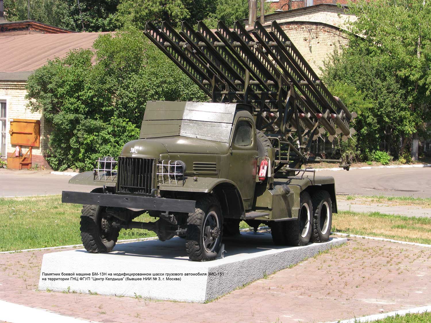
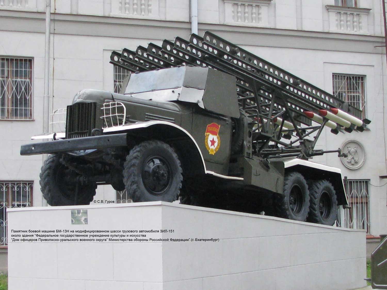
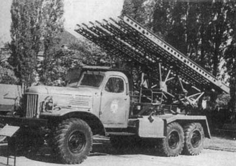
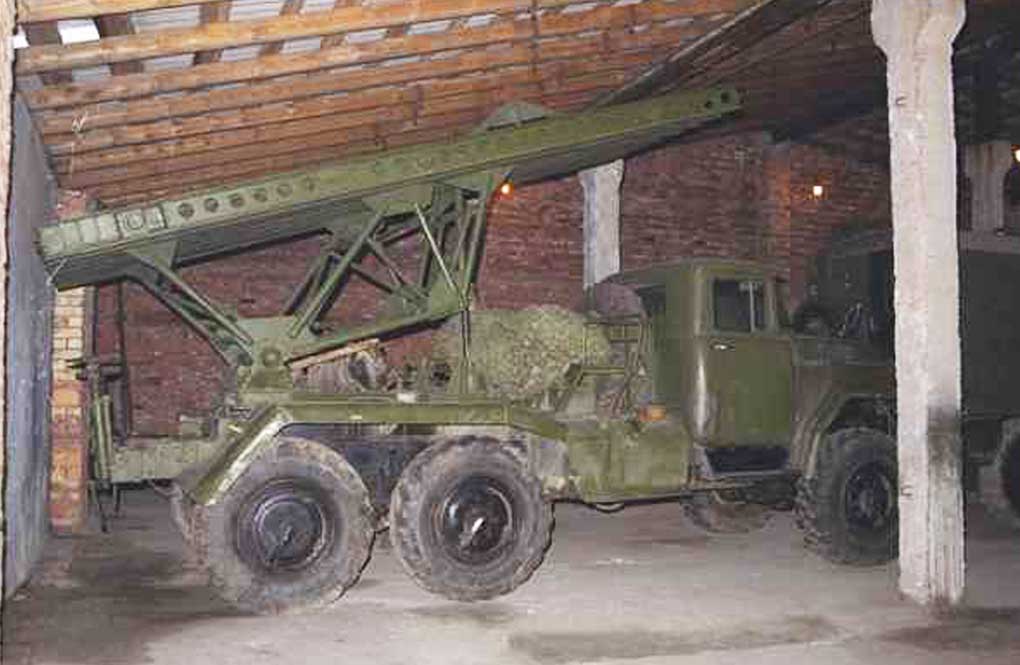
After the end of the Great Patriotic War one of the directions of the rocket artillery development was the use of throwing machines, developed during the war for installation on the modified types of chassis of domestic production. Several variants were created on the basis of M-13N installation on the modified chassis of ZIS-151 (see photo), ZIL-151 (see photo), ZIL-157 (see photo), ZIL-131 (see photo).
M-13 type units were exported to different countries after the war. One of them was China (see photo from the military parade on the occasion of National Day 1956 in Beidjin, Beijing) [37].
In 1959, when working on the shell for the future M-21 Field Rocket System, the developers were interested in the issue of technical documentation for the production of M-13 RDF. Here is what was written in the letter to the deputy director on scientific part of Research Institute-147 (nowadays FSUE "SNPP "Splav" (Tula), signed by the chief engineer of plant ¹63 SSNH Toporov (State plant ¹63 Sverdlovsk Sovnarkhoz, 22.VII.1959). ¹1959с): "On your inquiry for ¹3265 from 3/UII-59г. about sending of the technical documentation on manufacture РОФС М-13 I inform, that now the factory does not let out this product, from the technical documentation the vulture of privacy is removed.
At factory there are out-of-date pebbles of technological process of mechanical processing of a product. The factory has no other documentation.
In connection with loading of the light-copying device the album of technical processes will be shaded to you and sent not earlier as in a month"[38].
Composition:
Main composition:
- M-13 installations (combat vehicles M-13, BM-13) (see the M-13 image gallery) .
- M-13, M-13UK, M-13UK-1 main rockets.
- Machines for ammunition transportation (transport vehicles).
The M-13 projectile (see diagram) consisted of two main parts: a combat unit and a reactive part (a reactive powder engine). The combat unit consisted of a case with a point under the fuse, the bottom of the head unit and a bursting charge with an additional detonator. The projectile's reactive powder engine consisted of a chamber, a nozzle cap closing to seal the powder charge with two cardboard plates, a grate, a powder charge, an igniter and a stabilizer. On the outer part of both ends of the chamber there were two centring pins with screwed-in guide pins. The guide pins held the projectile on the war machine guide until the shot was fired and guided it along the guide rail. A nitroglycerine gunpowder charge was placed in the chamber, consisting of seven identical cylindrical single-channel draughts. In the nozzle part of the chamber checkers were resting on the grate. To ignite the gunpowder charge, a smoke gun ignition device was placed in the upper part of the chamber. Gunpowder was placed in a special case. Stabilization of M-13 projectile in flight was carried out with the help of tail plumage.
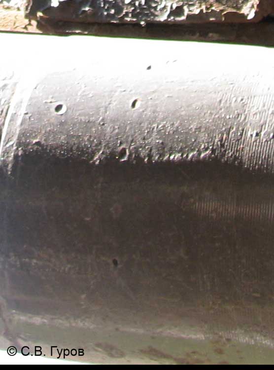
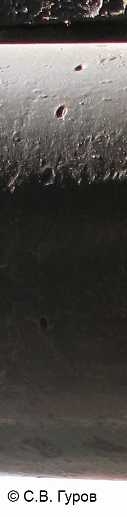
The flight range of the M-13 projectile reached 8470 m, but there was a very significant dispersion. In 1943, an upgraded version of the rocket was developed, which was designated M-13-UK (improved heap). To increase the heap rate of fire of the M-13-UK projectile, 12 tangentially located holes were made in the front centering thickening of the rocket part (see Photo 1, Photo 2), through which during the operation of the rocket engine part of the powder gases, which drives the projectile into rotation. Although the projectile's range of flight was slightly reduced (to 7.9 km), the improvement in heap size resulted in a smaller scattering area and a 3-fold increase in fire density compared to M-13 rounds. In addition, the critical cross-section diameter of the M-13-UK projectile is slightly smaller than that of the M-13. The M-13-UK was adopted by the Red Army in April 1944. The upgraded M-13UK-1 was equipped with flat stabilizers made of steel sheet. Translated with www.DeepL.com/Translator (free version)
Characteristics:
| Feature | М-13 | BМ-13Н | BМ-13NМ | BМ-13NММ |
| Chassis | ZIS-6 | ZIS-151,ZIL-151 | ZIL-157 | ZIL-131 |
| Number of guides | 8 | 8 | 8 | 8 |
| Angle of elevation, hail: - minimum - maximum |
+7 +45 |
8±1 +45 |
8±1 +45 |
8±1 +45 |
| Angle of horizontal fire, hail: - to the right of the chassis - to the left of the chassis |
10 10 |
10 10 |
10 10 |
10 10 |
| Force on the handle, kg: - lifting mechanism - tilting mechanism |
8-10 8-10 |
till 13 till 8 |
till 13 till 8 |
till 13 till 8 |
| Dimensions in camping position, mm: - length - width - altitude |
6700 2300 2800 |
7200 2300 2900 |
7200 2330 3000 |
7200 2500 3200 |
| Weight, kg: - guide packages - artillery unit - firing positions - trekking gear (no calculation) |
815 2200 6200 - |
815 2350 7890 7210 |
815 2350 7770 7090 |
815 2350 9030 8350 |
| Time to move from camping to combat, mines. | 2-3 | |||
| The time it takes to charge a combat vehicle, mines. | 5-10 | |||
| Full salvo time, sec | 7-10 | |||
| Main tactical and technical data of BM-13 combat vehicle (on Studebaker) 1946 [34]. | |
| Number of guides | 16 |
| Used projectile | M-13, M-13-UK and 8 shells. М-20 |
| Guide lengths, m | 5 |
| Type of guide | direct |
| Minimum elevation angle, ° | +7 |
| Maximum elevation angle, ° | +45 |
| Angle of horizontal guidance, ° | 20 |
| Lifting crank handle force, kg | 8 |
| Also, on the swivel mechanism, kg. | 10 |
| Overall dimensions, kg: | |
| length | 6780 |
| altitude | 2880 |
| width | 2270 |
| Weight of guideway set, kg | 790 |
| Weight of art part without shells and without chassis, kg | 2250 |
| Weight of combat vehicle without shells, without calculation, with full refueling of gasoline, snow chains, tools and spare wheel, kg | 5940 |
| Weight of a set of shells, kg | |
| M13 and M13-UK | 680 (16 shells) |
| М20 | 480 (8 shells) |
| The weight of the fighting vehicle with the calculation of 5 people. (2 in the cabin, 2 on rear fenders and 1 on gasoline) with full refueling, tools, snow chains, spare wheel and shells M-13, kg. | 6770 |
| Axle loads from the weight of the combat vehicle with the calculation of 5 people, full refueling with ZIP and shells M-13, kg: | |
| at the front | 1890 |
| at the back of | 4880 |
| Basic data of BM-13 combat vehicles | ||||
| Feature | BM-13N on the modified chassis of truck ZIL-151. | BM-13 on the modified chassis of truck ZIL-151. | BM-13H on the modified chassis of the truck series Studebaker | BM-13 on the modified chassis of the truck series Studebaker |
| Number of guides* | 16 | 16 | 16 | 16 |
| The length of the guideway, m | 5 | 5 | 5 | 5 |
| Largest elevation angle, hail. | 45 | 45 | 45 | 45 |
| Smallest elevation angle, hail. | 8±1° | 4±30' | 7 | 7 |
| Horizontal aiming angle, hail. | ±10 | ±10 | ±10 | ±10 |
| Lifting crank handle force, kg | till 12 | till 13 | till 10 | 8-10 |
| Turning handle force, kg | till 8 | till 8 | 8-10 | 8-10 |
| Weight of guide package, kg | 815 | 815 | 815 | 815 |
| Weight of the artillery unit, kg | 2350 | 2350 | 2200 | 2200 |
| Weight of combat vehicle in camping position (without people), kg | 7210 | 7210 | 5520 | 5520 |
| Weight of combat vehicle in combat position with shells, kg | 7890 | 7890 | 6200 | 6200 |
| Length in camping position, m | 7,2 | 7,2 | 6,7 | 6,7 |
| Width in camping position, m | 2,3 | 2,3 | 2,3 | 2,3 |
| Height in hiking position, m | 2,9 | 3,0 | 2,8 | 2,8 |
| Time to move from camping to combat, mines. | 2-3 | 2-3 | 2-3 | 2-3 |
| The time it takes to charge a combat vehicle, mines. | 5-10 | 5-10 | 5-10 | 5-10 |
| Time required to produce the salvo, sec. | 7-10 | 7-10 | 7-10 | 7-10 |
| Combat Vehicle Index | 52-U-9416 | 8U34 | 52-U-9411 | 52-ТR-492B |
* The author of the material. It means the number of guide gutters. The number of guides was 8, but each guide had two guide chutes - one at the top and one at the bottom.
| NURS M-13, M-13UK, M-13UK-1 | |
| Ballistics Index | ТS-13 |
| Header type | shrapnel-foot |
| Fuse type | GVMZ-1 |
| Caliber, mm | 132 |
| The full length of the projectile, mm | 1465 |
| Swing of stabilizer blades, mm | 300 |
| Weight, kg: - final charge - harnessed head end - bursting header - gunpowder charge - cascaded jet engine |
42.36 21.3 4.9 7.05-7.13 20.1 |
| projectile weight factor, kg/dm3 | 18.48 |
| Filling ratio of the head end, % | 23 |
| The power of the current needed to ignite the pyrophatron, A | 2.5-3 |
| Powder charge burning time, sec | 0.7 |
| Average reactive force, kgs | 2000 |
| Roll rate of the projectile off the guide rail, m/s | 70 |
| The length of the active section of the trajectory, m | 125 |
| Maximum projectile flight speed, m/s | 355 |
| Tabular maximum projectile range, m | 8195 |
| Deviation at maximum range, m: - at maximum range, m: in terms of distance - side |
135 300 |
| Powder charge burning time, sec | 0.7 |
| Average reactive force, kg | 2000 (1900 for M-13UK and M-13UK-1) |
| Muzzle velocity of the projectile, m/s | 70 |
| The length of the active section of the trajectory, m | 125 (120 for M-13UK and M-13UK-1) |
| Highest projectile velocity, m/s | 335 (for M-13UK and M-13UK-1) |
| The longest projectile range, m. | 8470 (7900 for M-13UK and M-13UK-1) |
According to the English catalog of Jane's Armour and Artillery 1995-1996, section Egypt, in the mid-90s, due to the impossibility of obtaining, in particular, shells for M-13 type combat vehicles, the Arab Organization for Industrialization was engaged in the production of 132 mm caliber rockets. An analysis of the data presented below leads to the conclusion that this was an M-13UK type projectile.
The Arab Organization for Industrialization consisted of Egypt, Qatar and Saudi Arabia, with the majority of production facilities located in Egypt and with major funding from Gulf countries. Following an Egyptian-Israeli agreement in mid-1979, the other three Gulf members withdrew their funds for the Arab Organization for Industrialization, and at that time (data from Jane's Armour and Artillery 1982-1983) Egypt was receiving other project assistance.
| Characteristics of 132 mm caliber Sakr projectile (RS type M-13UK) | |
| Caliber, mm | 132 |
| Length, mm | |
| full charge | 1500 |
| header | 483 |
| rocket engine | 1000 |
| Weight, kg: | |
| launch | 42 |
| header | 21 |
| fuze | 0,5 |
| rocket engine | 21 |
| fuel charges | 7 |
| Maximum plumage spread, mm | 305 |
| Header type | shrapnel-flag (with 4.8 kg of explosives) |
| Fuse type | inertial, contact |
| Type of fuel (charge) | binary |
| Maximum range (at an elevation angle of 45º), m | 8000 |
| Maximum projectile speed, m/s | 340 |
| Fuel burning time (charge), s | 0,5 |
| projectile velocity when encountering an obstacle, m/s. | 235-320 |
| Minimum detonation speed, m/s | 300 |
| Distance from the fighting vehicle to detonate the fuse, m | 100-200 |
| Number of sloping holes in the rocket motor housing, pcs. | 12 [46] |
Testing:
The first battery of field reactive artillery sent to the front on the night of July 1-2, 1941 under the command of Captain I.A.Flerov, was armed with seven units made in the workshops of Research Institute № 3. With its first salvo at 15 hours 15 minutes on July 14, 1941 the battery wiped the railway junction of Orsha off the face of the earth together with German trains with troops and military equipment.
The exceptional efficiency of the battery of Captain I.A. Flerov and the seven other batteries formed after him contributed to the rapid increase in the rate of production of reactive armaments. Already in the autumn of 1941, 45 battalions of three-battery personnel with four battery launchers were operating at the fronts. In 1941, 593 M-13 units were manufactured for their armament. With the arrival of military equipment from the industry, the formation of reactive artillery regiments, consisting of three divisions armed with M-13 launchers and an anti-aircraft division began. The regiment had 1414 personnel, 36 M-13 launchers and 12 anti-aircraft 37-mm guns. The salvo of the regiment was 576 shells of 132 mm caliber. In this case, the enemy's manpower and military equipment was destroyed on the area of more than 100 hectares. Officially, the regiments were called Guards Mortar Regiments of Artillery Reserve of the Supreme Command. Unofficially, the rocket launchers were called "Katyusha". According to the memoirs of Yevgeny Martynov (Tula), a former child during the war, they were initially called hellenic machines in Tula. From ourselves we shall note, that multicharger machines also called hell cars in XIX century.
Sources:
- Шунков В.Н. 'Ракетное оружие',изд."ПОПУРРИ",Минск,2001 г.
- БМ-13 «Катюша» /Интернет-проект 'Русская сила'/
- БМ-13Н /'Великая война'/
- Гвардейская "Катюша"
- ГНЦ ФГУП “Центр Келдыша”. Оп. 1. Ед.хр.по описи.12. Инв.225. Л.39.
- ГНЦ ФГУП “Центр Келдыша”. Оп. 1. Ед.хр.по описи.12. Инв.225. Л.108.
- ГНЦ ФГУП “Центр Келдыша”. Оп. 1. Ед.хр.по описи.8. Инв.227. ЛЛ.55,58,61.
- ГНЦ ФГУП “Центр Келдыша”. Оп. 1. Ед.хр.по описи.8. Инв.227. ЛЛ.94,96,98.
- ГНЦ ФГУП “Центр Келдыша”. Оп. 1. Ед.хр.по описи 13. Инв.273. Л.228.
- ГНЦ ФГУП “Центр Келдыша”. Оп. 1. Ед.хр.по описи.13. Инв.273. Л.231.
- ГНЦ ФГУП “Центр Келдыша”. Оп. 1. Ед.хр. по описи 14. Инв. 291. ЛЛ.134-135.
- ГНЦ ФГУП “Центр Келдыша”. Оп. 1. Ед.хр. по описи 14. Инв. 291. ЛЛ.53,60-64.
- ГНЦ ФГУП “Центр Келдыша”. Оп. 1. Ед.хр. по описи 22. Инв. 388. Л.145.
- ГНЦ ФГУП “Центр Келдыша”. Оп. 1. Ед.хр. по описи 14. Инв. 291. ЛЛ.124,134.
- ГНЦ ФГУП “Центр Келдыша”. Оп. 1. Ед.хр. по описи 16. Инв. 376. Л.44.
- ГНЦ ФГУП “Центр Келдыша”. Оп. 1. Ед.хр. по описи 24. Инв. 375. Л.103.
- ЦАМО РФ. Ф. 81. Оп. 119120сс. Д. 27. Л. 99, 101.
- ЦАМО РФ. Ф. 81. Оп. 119120сс. Д. 28. Л. 118-119.
- Ракетные пусковые установки в Великой Отечественной войне. О работе в годы войны СКБ при московском заводе “Компрессор”. // А.Н. Васильев, В.П. Михайлов. – М.: Наука, 1991. – С. 11–12.
- "Моделист-Конструктор" 1985, №4
- ЦАМО РФ: Из истории начального этапа формирования гвардейских минометных частей (М-8,М-13)
- ЦАМО РФ: К вопросу о захвате “Катюши
- Гуров С.В."Из истории создания и развития полевой реактивной артиллерии в СССР в период Великой Отечественной войны"
- Первицкий Ю.Д., Слесаревский Н.И., Шульц Т.З., Гуров С.В. "О роли систем реактивной артиллерии (РСЗО) для сухопутных войск в мировой истории развития ракетного вооружения в интересах военно-морских флотов"
- Боевая машина М-13. Краткое руководство службы. М.: Главное артиллерийское управление Красной армии. Военное издательство Народного комиссариата обороны, 1945. - С. 9,86,87.
- Краткая история СКБ-ГСКБ Спецмаш-КБОМ. Книга 1. Создание ракетного вооружения тактического назначения 1941-1956 гг., под редакцией В. П. Бармина - М.: Конструкторское бюро общего машиностроения. - С. 26, 38, 40, 43, 45, 47, 51, 53.
- Боевая машина БМ-13Н. Руководство службы. Изд. 2-е. Воениздат МО СССР. М. 1966. - С. 3,76,118-119.
- ЦАМО РФ. Ф. 81. Оп. А-93895. Д. 1. Л. 10.
- Широкорад А.Б. Отечественные минометы и реактивная артиллерия.// Под общей редакцией А.Е. Тараса. – Мн.: Харвест, М.: ООО “Издательство АСТ”, 2000. – С.299-303.
- http://velikvoy.narod.ru/vooruzhenie/vooruzhcccp/artilleriya/reaktiv/bm-13-sn.htm
- ГНЦ ФГУП “Центр Келдыша”. Оп. 1. Ед.хр. по описи 14. Инв. 291. Л. 106.
- ГНЦ ФГУП “Центр Келдыша”. Оп. 1. Ед.хр.по описи 19. Инв. 348. Л. 218,220.
- ГНЦ ФГУП “Центр Келдыша”. Оп. 1. Ед.хр.по описи 19. Инв. 348. Л. 224,227.
- ГНЦ ФГУП “Центр Келдыша”. Оп. 1. Ед.хр.по описи 19. Инв. 348. Л. 21. Копия.
- ЦАМО РФ. Ф. 81. Оп. 160820. Д. 5. Л. 18-19.
- Боевая машина БМ-13-СН. Краткое руководство. Военное министерство Союза ССР. - 1950.
- http://www1.chinadaily.com.cn/60th/2009-08/26/content_8619566_2.htm
- ГАУ ТО "ГА". Ф. Р3428. Оп. 1. Д. 449. Л. 49.
- Константинов. О боевых ракетах. Санкт-Петербург. Типография Эдуарда Веймара, 1864. – С.226-228.
- ГНЦ ФГУП “Центр Келдыша”. Оп. 1. Ед.хр. по описи 14. Инв. 291. Л. 62,64.
- ГНЦ ФГУП “Центр Келдыша”. Оп. 1. Ед.хр. по описи. 2. Инв. 103. Л. 93.
- Лангемак Г.Э., Глушко В.П. Ракеты их устройство и применение. ОНТИ НКТП СССР. Главная редакция авиационной литературы. Москва-Ленинград, 1935. - Заключение.
- Ивашкевич Е.П., Мудрагеля А.С. Развитие реактивного оружия и ракетных войск. Учебное пособие. Под редакцией доктора военных наук, профессора С.М. Бармаса. - М.: Министерство обороны СССР. - С. 41.
- Боевая машина БМ-13Н. Руководство службы. М.:Воениздат. - 1957. - Приложение 1,2.
- Боевые машины БМ-13Н, БМ-13НМ, БМ-13НММ. Руководство службы. Третье издание, исправленное. М.: Воениздат, - 1974. – С. 80, Приложение 2.
- Jane's Armour and Artillery 1982-1983. - Р. 666.
- Jane's Armour and Artillery 1995-96. - Р. 723.
- ЦАМО РФ. Ф. 59. Оп. 12200. Д. 4. Л. 240-242.
- Первов М. Рассказы о русских ракетах. Книга первая. – Издательский дом "Столичная энциклопедия". – Москва, 2012. – С. 257.
