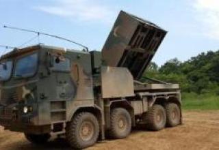
The BM-13-SN combat vehicle was a further improvement of the launchers for firing 132-mm M-13 rockets as well as the new M-13-DD-1.
Production of prototypes of BM-13-SN was carried out at the Moscow plant "Compressor" (№ 733). The prototypes were successfully tested on a range and on the road, after which the plant went into mass production. In 1945, the plant "Compressor" was made several divisions, designed for use in the storming of Berlin, for which a special military unit was created under the command of Major RB Vannikov.
After the end of the war in 1945, the installation of BM-13-SN passed military tests. Good results were shown, however, due to the forthcoming modernization of M-13 type rockets, the unit was not adopted for service. After the 1946 series it was taken out of production (NKOM Order No 27 of 24.10.1946). However, in 1950 the BM-13-SN Short Guide to the combat vehicle was produced.
Based on the directive of the Deputy Commander of the Artillery of the Armed Forces ¹ 348212ss of 05.04.46 in the period from May 10 to June 10, 1946 at the Sofrinsky art polygon were carried out military tests of combat vehicles BM-8-SN and repeated military tests BM-13-SN (see gallery). The tests were conducted under the chairmanship of the Head of the 6th Faculty of the Artillery Academy, Lieutenant-General of Artillery Kuleshov P.N. The division of the 22nd Separate Guards Mortar Regiment of Polotsk Red Banner Regiment was assigned to provide military testing. Four combat vehicles BM-8-SN and BM-13-SN of the design and manufacture of plant № 733 MMiP were tested. Firing and mileage tests on combat vehicles were conducted in parallel with regular BM-8-48 and BM-13 combat vehicles.
During the tests, the following combat firing tasks were performed:
- Direct-fire from a single combat vehicle (BM-8-CN and BM-13-CN) at an elevation angle of 6°-7° and 10°-10° to determine the smallest angle of sight, which ensures the safety of numbers and the smallest angle of sight when shooting through the cab (4 firing);
- firing of a conventional combat vehicle (new and standard) to determine the heap of combat at the maximum range (elevation angle - 45°) and medium range (elevation angle 21° - only for BM-13-CN) - 21 shots in total.
- battery-powered firing from new and standard combat vehicles to determine the dispersion area and density of battery volley fire (16 firings).
BM-13-CN was fired from M-13, M-13-UK (improved heap); M-20 (high-explosive) and M-13-DD (long-range) rounds, and only M-13-UK and M-20 from regular BM-13s.
The results of the military tests:
When shooting with direct fire from BM-13-CN, the smallest angle of elevation ensuring safety of shooting with the machine's digging forward was an angle of 6°, at which the breaks were not closer than 300 meters from the firing position.
The BM-13-SN combat vehicle had the following advantages compared to the standard BM-13:
- When the BM-13-CN was fired with the M-13 (cheaper) projectile, the dispersion was reduced to the sizes almost identical to the dispersion of the standard BM-13 when the M-13-UK projectile was fired. Average range of the new BM-13-CH with the M-13 round at the elevation angles of 21º and 45º is 600 m higher on average as compared to the range of the M-13-UK rounds from the standard BM-13;
- When the BM-13-CH was fired with the M-13-UK projectile, the dispersion was reduced by 10% as compared with the dispersion of the M-13 projectiles when fired from the same combat vehicle;
- When BM-13-CH was fired by M-20 rounds at the maximum range, the scattering area was reduced by 2 times, while the density of fire increased by 2.5 times.
- For BM-13-CN it was possible to fire M-13-DD projectiles with the maximum range up to 12 km (regular BM-13-CN does not withstand the firing of M-13-DD projectiles).
The following shortcomings of BM-13-CN were noted:
- Decrease in the number of barrels to 10 (instead of 16 of the standard one) resulted in 1.6 times less power and 40% less battery volley fire density (when firing M-13 and M-13-UK shells as compared to the standard BM-13 with M-13-UK shells). To obtain the density of the new BM-13-CN battery volley of the same density as the standard BM-13, it is necessary to use 1.5 battery volley and 1.7 volley of M-13-UK projectile when firing from BM-13-CN. ;
- The smallest angle of elevation of the BM-13-CN with undigged forward movement was 3° more than that of the standard BM-13, which increased the smallest direct-fire range by about 800 meters, allowing shooting from a range of 2700 m (with a 0º angle of fire). The standard BM-13, when fired under the same conditions, has advantages, as it can be fired at an elevation angle of 7º with a range of about 1900 meters.
- The impossibility to check the panorama reflector both in the BM-13-CN and in the standard BM-13, which is a big disadvantage for direct-fire shooting;
- The weight of the BM-13-CN artillery unit is 240 kg more than that of the standard BM-13;
- The height of the BM-13-CN is 250 mm more than that of the standard BM-13;
- Low vertical aiming speed;
- Incomfort of cleaning and lubrication of screw guides located in the center of the package;
- The stopper does not hold the projectiles enough on the hike - 6 projectiles in one BM;
- Replacement of the damaged barrel in the cassette requires replacement of the entire cassette in the workshop part.
M-13-DD shells were tested in 1944 by firing from regular BM-13 combat vehicles. The report on these tests concluded that it was impossible to use M-13-DD shells from BM-13 without hardening this machine. During BM-13-CN tests, M-13-DD missiles were tightly inserted into the guides (barrels) due to the axial curvature of the missiles.
In addition, at the assembly of deputy district commanders of the MHF, in June 1946, 79 shots were fired from BM-13-CN M-13-DD, of which there were 3 missiles (breaks at a range of 5 km) and 30 torn wings of the stabilizer on the trajectory.
When shooting at Sofrinsky range from 25.06.46 to 12.07.46 in the amount of 360 rounds of BM-13-CN, about 8% of M-13-DD projectiles fired had the stabilizer wings torn off.
In the BM-13-SN combat vehicle, as having a number of significant drawbacks, to eliminate the technical and main operational shortcomings noted in the report of the commission, to order a series of these machines in the amount of 12 pieces and subject them to wider tests in the troops.
It was decided to finalize the M-13-DD projectiles and submit them for military testing for firing from BM-13-SN combat vehicles.
Composition:
BM-13-CN was used for:
- the destruction of enemy life force located openly and behind light field shelters;
- the suppression and destruction of enemy firepower;
- destroying tanks and other enemy motorised vehicles in their concentration areas.
BM-13-CN combat vehicles were fired only at targets that occupied a significant area; the number of combat vehicles that were simultaneously fired was determined according to the task at hand.
The BM-13-CN fighting vehicle was sufficiently maneuverable to focus on an important direction in a short period of time, allowing a large number of combat vehicles and suddenly open fire. Due to the sudden and massive fire of combat vehicles BM-13-CN inflicted a serious defeat on the enemy and had a strong moral impact.
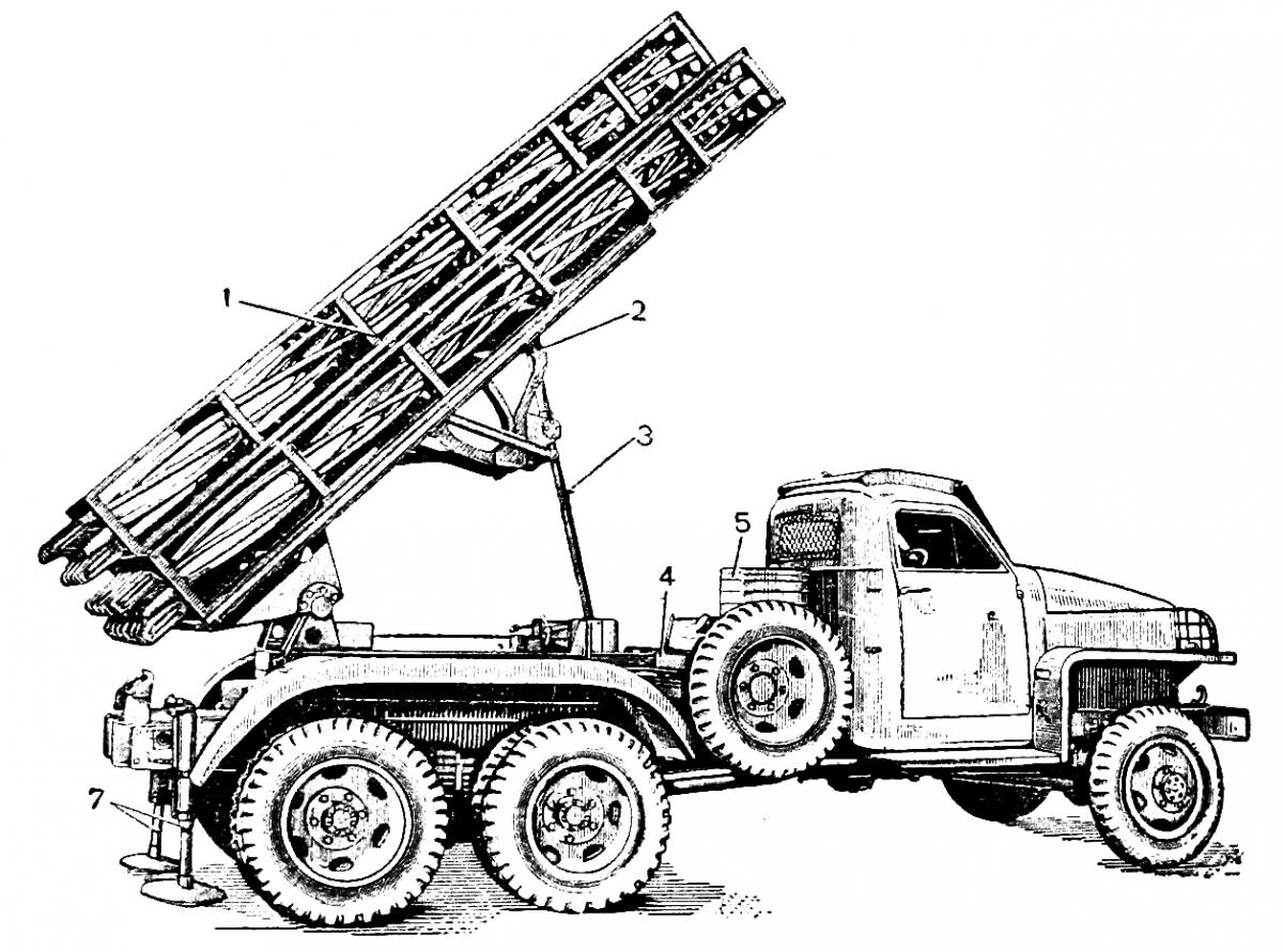
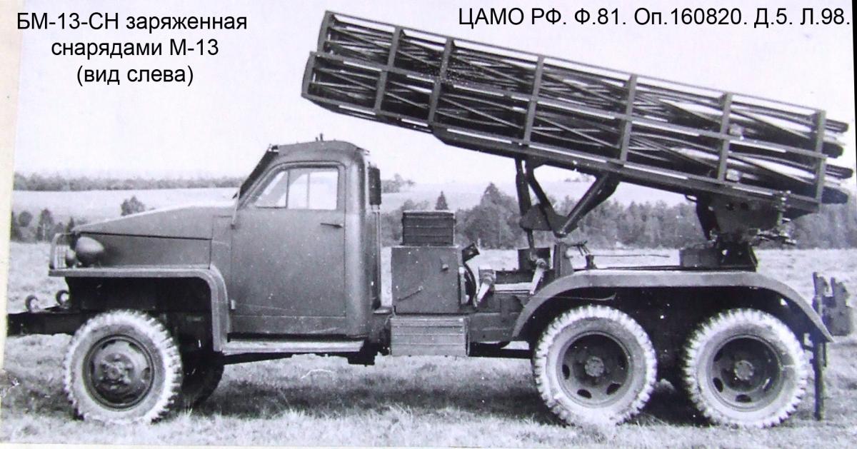
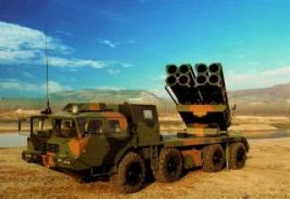
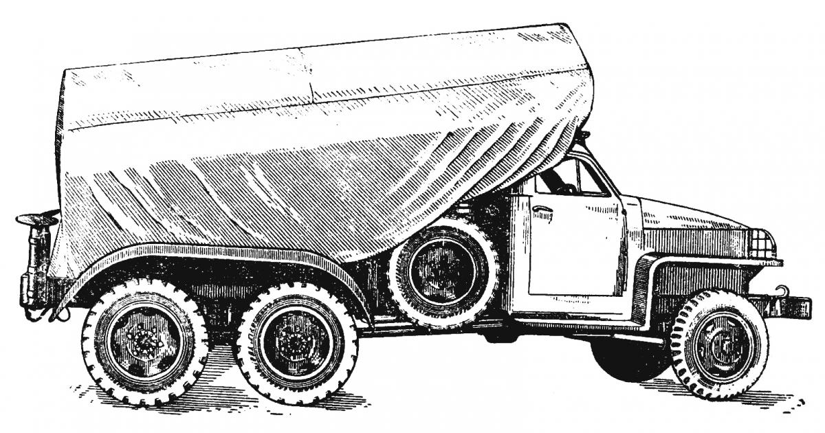
BM-13-SN fighting vehicle in combat position, loaded with M-13 shells:
- 1 - package of guide cells;
- 2 - a farm;
- 3 - lifting mechanism;
- 4 - swivel mechanism;
- 5 - battery box;
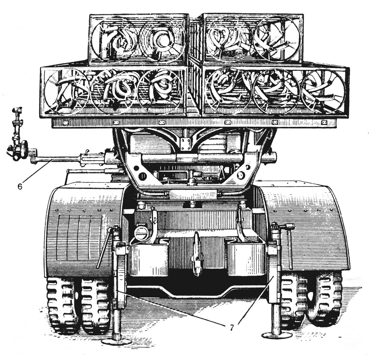
- 6 - sighting console;
- 7 - jacks.
BM-13-CN was a self-propelled artillery unit, consisting of the following main parts: package, farm, turning frame, base, lifting mechanism, swivel mechanism, special chassis equipment, electrical system for ignition of the charge, sighting devices and car chassis.
The BM-13-SN was intended for firing regular M-13 and M-13-DD, M-20 and M-13-UK missiles.
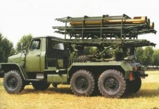
The combat vehicle had a set of spiral guides, mounted on the basis of the standard BM-13 (normalized) with a farm made of BM-31-12. Each spiral guide consisted of 3 tubes bent on a screw line and one leading guide, which was a square steel bar with grooves selected from two opposite sides and bent also on a screw line. One of the grooves is a worker in which there is a front pin of the projectile which informs him of the rotation when the shot is fired.
Three pipes and a guide rail attached to the cages with strips formed the barrel inside which the projectile was moving. The barrels were welded together into four cassettes. The upper two cassettes had two barrels each and the lower two cassettes had three barrels each, so the guide set consisted of 10 barrels.
Each barrel had a lock in the breech block, which kept the projectile from falling backwards and from advancing while walking forward. The stopper acted automatically. To discharge the projectile, the stopper was equipped with a handle that opened the projectile.
On the sides of the guide rail in the location of the lock were reinforced two electric contacts, one on the side by which the current from the batteries to the projectile pies. The electric contacts and the stopper were protected by a cover.
In the muzzle part of each barrel there were bevels at the guide rail and at one of the neighboring pipes to avoid hitting the rear (not working) pin of the projectile when it comes out of the barrel. The cassettes were detachable and bolted on the farm.
Package 1 consisted of ten spiral guides cells designed to release the projectile. The guide cells were mounted in four cassettes, which were reinforced on the farm in two rows.
Farm 2 was a grating platform, welded from coal. The farm, together with a packet of guide cells, could rotate in a vertical plane with respect to the axis, located in the sleeves of the brackets of the turning frame.
The swing frame consisted of a frame welded from channels and two brackets. Together with the frame and the guide package, it rotated in a horizontal plane around the axis, which was reinforced on the base.
The base was a rectangular frame, welded from channels and fixed to the spars of the vehicle chassis. All major components of the artillery unit were mounted on the base.
Lifting 3 and pivoting 4 mechanisms were screw type. With the help of the lifting mechanism, a package of guide cells could be given elevation angles from +10° to +45°. With the help of the rotary mechanism the horizontal alignment angle of the guide package was changed within 10° (left and right) from the central position.
Special equipment of the chassis consisted of protection of the cabin and gas tank, jacks, a box for ZIP and a battery box. Cabin protection protected the cabin and the calculation located in it from the gas jet of projectile when the shot was fired.
Jacks 7 provided for horizon leveling of the farm axis when the fighting vehicle was installed on uneven ground. In addition, the jacks reduced vibrations of the fighting vehicle when firing.
Battery box 5 housed two 5-NKN-45 alkaline batteries, which served as a source of power to the electrical system for ignition of the charge. This system consisted of two 5-NKN-45 alkaline batteries, a switch, a switch, a switch, a junction box and a wiring system. With the help of the switch, the current through the switch, the junction box and the wiring system was brought to the contacts of the guide cells and provided for ignition of projectile pyropatrons.
Sighting devices included: sight from 76-mm gun rev. 1942. panorama and group of transition parts.
The package, farm, turning frame, base, aiming mechanisms, sights and electric system for ignition of the charge made up the artillery part of the combat vehicle. The artillery part was mounted on the vehicle chassis and was covered with a tarpaulin cover to protect it from dust, dirt and rain in a hiking position (see diagram).
Characteristics:
| Main data of BM-13-SN combat vehicle | |
| Number of Guidance Cells | 10 |
| The length of the guide cells, m | 4 |
| Inner diameter of cells, mm | 132,8 |
| The highest elevation angle, ° | +45 |
| The smallest elevation angle, ° | +10 |
| Angle of horizontal firing, ° | ±10 |
| Lifting crank handle force, kg | 10-12 |
| Turning handle force, kg | 10 |
| Weight of the guide package, kg | 1150 |
| Weight of the artillery unit, kg | 2470 |
| Weight of BM-13-CN in camping position (without shells), kg: | 6250 |
| Weight of BM-13-SN in combat position, kg: | |
| with M-13 or M-13-UK shells | 6680 |
| with M-13-DD-1 missiles | 6880 |
| Length in hiking position, mm | 6365 |
| Width in hiking position, mm | 2200 |
| Height in hiking position, mm | 3115 |
| Time of transition from camping to combat, min. | 1,5-2 |
| The time it takes to charge a combat vehicle, min.: | |
| M-13 or M-13-UK shells | 2,0-2,5 |
| M-13-DD-1 shells | 3,0-5,0 |
| Time required to produce the salvo, sec. | 5-7 |
Testing:
The first launches of K-10 in marine aviation were made by North Sea crews on the Caspian Sea in July 1960. Having departed from the airfield of the 33rd Center near Nikolaev, a pair of Tu-16K-10s reached the target, and from a height of 10,000 m at a range of 175 km the crew of Colonel Myznikov made the launch. Due to a pointing error, the missile did not reach the target, having fallen into the sea at 40 km, the crew of Lieutenant Colonel Kovalev, who followed, attacked from a distance of 170 km, achieving a direct fall into the target - the tanker "Chkalov" drowned in shallow water. Within two weeks, three more attacks were carried out, one of which again failed due to operator's error, and in one missile hit the crest of the wave just 200 m from the ship.
The training and combat launches were accompanied by supervision of industry representatives - nevertheless, the system was accepted with many reservations and required prompt correction of defects. For this purpose, even a special design and technological bureau (SCTB) was organized with participation of engineers from MAP, Design Bureau, Research Institute and AUMF. The researches carried out on the basis of the 33rd Center showed the practical feasibility of target detection from 450 km by adjusting the frequencies and length of the radar pulses. It was possible to launch long-range missiles from 325 km, and the lower limit of the aircraft flight was 500-600 m. The radar antenna of the carrier carried out scanning, mechanically rotating through the azimuth of 120 °, making it possible to turn away from the target after launch and continue to provide escort. Usually, the turn-off was performed at the 100th second with a roll of 9-12°, dictated by the possibility of stabilization of the antenna. Approximation to the target, depending on the flight mode and altitude of the launch, did not exceed 140-160 km (later withdrawal from the attack at the start of K-10SD from the maximum range could be carried out at a distance of 265 km).
In one of the departures for tactical launch in 1961, the crew of Captain G.A.Zimin faced an emergency situation, when the missile released into the starting position could not be returned. Nothing good landed with a hanging missile did not promise, because with a normal landing angle of 8 °, there was a great risk of "combing" the missile on the ground. Nevertheless, the crew managed to get the plane to land successfully, and then the instructions for such a case were introduced in the pilot's instructions.
In 1960-62, the K-10 missile system was equipped with seven air regiments of all Soviet fleets: 2nd MRAD of the Black Sea, 5th MRAD of the North, 25th and 143rd MRAD of the Pacific and 57th MRAD of the Red Banner Baltic Fleet. The intensity of development and combat training of maritime aviation crews looked impressive: for the first six months of operation in 1960 there were 79 launches, the next - 126, and in 1962 - 147 (however, the reverse side was a large consumption of combat missiles, and a duplicate aircraft like "Kometa", which allows you to save money and expensive products, for the K-10 was not available).
Another shortcoming was revealed - poor preparedness of ground services for operation of complex equipment. At first, it was assigned to a special engineering and aviation service of SIS, and the issues of warehousing, engaged in repair and maintenance base. Getting rid of duplication of work, the structure was reorganized and introduced a division of responsibilities: all systems of the aircraft were serviced by IAS specialists regiment, and the full list of work on missiles was carried out by the maintenance base.
The measures taken allowed reducing the time of equipment preparation and improving the quality of work. The confirmation was the reduction of the number of unsuccessful launches due to mistakes in the preparation of the mattress - already in 1962, their number decreased by 20%. Near the aircraft were equipped with shelters, where there were refueled and equipped with missiles, pre-tested and flying in the air on "its" carrier. The procedure of suspension and preparation of K-10 was reduced to 45 minutes, and this work was fully carried out by regimental technicians and crews - preparation for the departure of two squadrons with 16 Tu-16K-10 reduced in time by half.
We managed to reduce the number of failures, although the number of complaints about the shortcomings and defects of the system remained tangible, so the reliability of the Tu-16K-10 was inferior to other, simpler complexes, primarily through the fault of the equipment. In 1961, almost half of the completed launches failed, and about a third - due to design and manufacturing flaws.
Face-to-face with Soviet missile carriers, the United NATO Fleet had to meet in September 1964 during a major exercise "Tim Work-64", covering the entire North Atlantic. More than half a dozen ships, including two aircraft carrier groups, participated. The squadron was discovered by Tu-95 reconnaissance aircraft of the Northern Fleet, after which the command of the 5th MRAD offered to organize a response exercise with the use of aviation "on real targets", showing, for example, the head of the country to the Americans "Kuzkinu mother". Command of the Navy, however, was afraid of bringing the situation to the brink of unleashing a real war, but the top leadership of the country gave the conceived "good".
By order of the Air Force Headquarters of the NF plan was adopted for implementation. In the evening of September 21, three squadrons of Tu-16K-10 strike team of Lieutenant Colonel KL Timakov, as well as scouts, designators and interference operators who were covering the missile carriers. The ship's group was found in the ocean, the planes at low altitude stealthily reached the border of the attack. The "missile strike" was launched from three directions with a distance of 160-200 km, and the enemy was helpless to repel it.
At TOF in 1964 there was a case of attack K-10S Japanese ship, which was in the restricted zone of the range. Shino-Maru" was held near Cape Tyk, where the crew of Tu-16K-10 from the 169th MRAP worked out a training task. Having refocused, the rocket went exactly on a new "target". The Japanese were lucky - the fuse was set to detonate on the trajectory to save the targets, and the explosion occurred 400 meters from the board. The wreckage damaged the superstructure and the rocket's engine broke through the ship. Among the crew were wounded, which forced the Japanese to go to the nearest Soviet port of Kholmsk for medical care and repair. The incident managed to jam, and the Japanese side believed that the ship was hit by a crashed Soviet fighter, and expressed sympathy for the lost pilot.
During the largest strategic exercise "Ocean", held in April 1970 and covering all the fleets and water areas, the North Sea Tu-16K carried out 6 rocket launches at the range, thrown into reinforcements to them 10 missile carriers with TOF April 20 attacked the target missiles near the Kola Peninsula. Nine Tu-16K-10 of the Pacific 143rd MRAD, supported by five tankers, carried out tactical attacks in the Sea of Japan, using groups of NATO and U.S. ships as targets.
The Baltfleet's Tu-16K-10 was airborne when it intercepted the mutinous SCR "Storozheva," which left the base and headed for the Strait of Irben during the October 1975 holidays. It was supposed that he wanted to go abroad, and to stop this attempt on November 8 and 9 all forces of the fleet and aviation were alerted. Rocket attack in the area with busy shipping, fortunately, did not take place - Tu-16 found the target when the ship has already been bombed and stalled cars, but they accompanied him on the way back to the base.
With the organization of the base of the Soviet fleet in the Vietnamese port of Kamran there was placed 169th gv. SAP, which, in addition to scouts, target designation and anti-submarine aircraft, at the front positions was a squadron of Tu-16K-10-26. They served there from 1982 to 1989.
Sources:
- Боевая машина БМ-13-СН. Краткое руководство. Военное министерство Союза ССР. - 1950. - С.3-5,75.
- Краткая история СКБ-ГСКБ Спецмаш-КБОМ. 1 книга. Создание ракетного вооружения тактического назначения 1941-1956 гг. – М.: Конструкторское бюро общего машиностроения, 1967. – С.55.
- ЦАМО РФ. Ф.81. Оп.160820. Д.5. ЛЛ.2-10,16-19,37-39,46,47,51,55-57,98.
