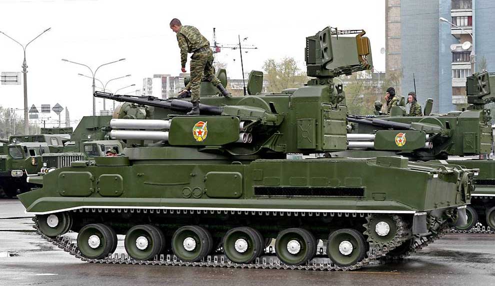
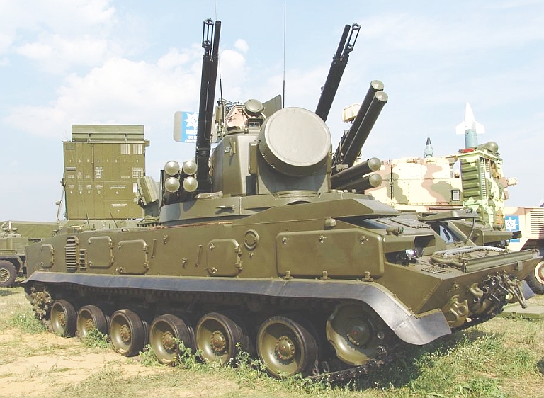
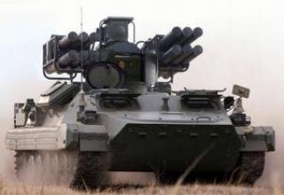
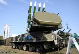
Anti-aircraft missile and gun system 2K22 "Tunguska" is designed for air defense of motorized rifle and tank units on the march and in all types of combat, provides defeat of low-flying air targets, including "hung" helicopters. It was adopted for service in the mid-1980s. The combat vehicle has a turret unit with two twin-barreled 30 mm automatic guns and eight launchers with anti-aircraft guided missiles.
The development of the complex "Tunguska" was entrusted to the Design Bureau of Instrument Engineering (KBP) MOE (Chief Designer A.G. Shipunov) in cooperation with other organizations of defense industries Decree of the CPSU Central Committee and the USSR CM on June 8, 1970 and initially provided for the creation of a new antiaircraft gun self-propelled installation (ZSU) to replace the famous "Shilke" (ZSU-23-4).
Despite the successful use of "Shilka" in wars in the Middle East, these hostilities revealed its shortcomings - low reach to targets (no more than 2 km in range), poor penetration of projectiles, as well as the fact that air targets are not fired due to the inability to detect in time. The expediency of increasing the calibre of automatic anti-aircraft guns was worked out. Experimental studies have shown that the transition from a 23 mm to a 30 mm projectile with a two to three times increase in explosive weight allows you to 2-3 times reduce the number of hits needed to hit the aircraft. Comparative calculations of the combat effectiveness of the ZSU-23-4 and the hypothetical ZSU-30-4 when shooting at the MiG-17 fighter flying at 300 m/s have shown that with the same mass of the consumed ammunition the probability of hitting the aircraft increases by about one and a half times, the reach in altitude - from 2000 to 4000 meters. As the caliber of the guns increases, so does the effectiveness of firing at ground targets, as well as the possibility of using cumulative projectiles to engage lightly armored targets such as infantry fighting vehicles in SSDs. The transition from the 23 mm to 30 mm anti-aircraft gun calibre had practically no effect on the rate of fire provided, but with the further increase in the calibre it was technically impossible to ensure high firing speed.
Shilka" sighting system had very limited search capabilities, provided by its radar to accompany targets in the sector 15:40 ° azimuth with simultaneous change of the angle of position within 7 ° from the specified antenna axis direction. The high effectiveness of the ZSU-23-4 was only achieved by obtaining preliminary target designation from the battery commander's PU-12 (PU-12M), which, in turn, used data from the division's air defense chief's office, which had a P-15 (P-19) all-around radar. Only then did the ZSU-23-4 radar successfully search for targets. In the absence of target designation, the airborne radar could perform an autonomous circular search, but the efficiency of detecting air targets was less than 20%. The NII-3 MO determined that in order to ensure the combat autonomous operation of the prospective ASU and its high effectiveness in shooting, it should have its own circular view radar with a range of 16-18 km (with a range measurement error of no more than 30 m RMS), and the view sector of this radar in the vertical plane should be at least 20°.
However, the advisability of developing an anti-aircraft missile system has caused great doubt in the Office of the USSR Minister of Defense AA Grechko. The reason for such doubts and even cessation of funding for further development of the Tunguska SAM system (in the period 1975-1977) was the fact that it was adopted in service in 1975. The Osa-AK" SAM system had a close in size airplane strike zone in range (up to 10 km) and larger than that of "Tunguska" SAM system, the size of the strike zone of aircraft height (0.025-5 km), as well as approximately the same characteristics of the effectiveness of aircraft destruction. But the specifics of armament of the Air Defense Regimental Division, for which the SAM was designed, as well as the fact that in the fight against helicopters "Osa-AK" SAM was significantly inferior to the Tunguska SAM, because it had a much longer working time - more than 30 seconds against 8-10 seconds at the Tunguska SAM. Short reaction time of Tunguska SAM system ensured successful fight against helicopters that appeared briefly ("jumping") or suddenly departed due to terrain folds and other low-flying targets, which Osa-AK could not provide.
In the Vietnam War, the Americans first used helicopters armed with anti-tank guided missiles (PTUR). It became known that 89 out of 91 helicopter attacks with anti-tank guided missiles were successful in attacking armored vehicles, artillery positions and other ground targets. Based on this combat experience in each division of the U.S. have created special helicopter units to combat armored vehicles. The Fire Support Helicopter Group, in conjunction with a reconnaissance helicopter, held a creased position 3-5 km from the combat line of contact. As the tanks approached it, the helicopters "jumped" up 15-25 m, hit the tanks with the help of PTUR, and then quickly fled. As a result of the research carried out, it was determined that the reconnaissance and defeat capabilities of modern tanks, as well as the overall weaponry used to engage ground targets in motorized rifle, tank and artillery formations, were unable to engage helicopters in the air. Wasp" SAMs can provide reliable cover for attacking tank units from aircraft attacks, but they are unable to protect tanks from helicopters. The positions of these SAMs will be up to 5-7 kilometres away from helicopter positions, which will "jump" when tanks attack, hovering in the air for no more than 20-30 seconds. According to the total reaction time of the complex and the flight time of the SAM system to the border of the location of the Osa and Osa-AK helicopters, the helicopter could not be hit by the SAM system. Arrow-2, Arrow-1 and Shilka SAM systems were also unable to fight with fire support helicopters with such tactics of their combat application. The only anti-aircraft vehicle that can effectively fight the hovering helicopters, could be SSD "Tunguska", which has the ability to escort the tanks as part of their combat orders, which had a sufficient long range of the affected area (4-8 km) and a short working time (8-10 seconds).
The development of the "Tunguska" complex as a whole was carried out by KBP MOP (Chief Designer A.G. Shipunov). The Chief Designers of Cannons and Missiles were V.P.Gryazev and V.M.Kuznetsov respectively. The main facilities of the complex were developed by the Ulyanovsk MRP Mechanical Plant (based on the radio equipment, Chief Designer Yu.E. Ivanov), Minsk Tractor Plant IMSM (based on the GM-352 tracked chassis with power supply system), All-Russian Research Institute "Signal" MOP (based on guidance systems, stabilization of the firing line and optical sight, navigation equipment), LOMO MOP (based on the sighting and optical equipment) and other organizations.
Joint (state) tests of the "Tunguska" complex were conducted from September 1980 to December 1981 at the Donguz test site. The complex was adopted by the Decree of the CPSU Central Committee and the USSR CM of September 8, 1982. Series production of "Tunguska" complexes and their modifications was organized at the Ulyanovsk MRF mechanical plant, cannon weapons - at the Tula mechanical plant of MRF, missile - at the Kirov Machine-Building Plant "Mayak" MRF, sighting and optical equipment - at LOMO MRF. The Minsk Tractor Plant IMSM supplied tracked self-propelled vehicles (with support systems).
By the middle of 1990 the "Tunguska" complex was modernized and received the designation "Tunguska-M" (2K22M). From August to October 1990, the 2K22M complex was tested at the Emba test site under the guidance of a commission headed by A.Y. Belotserkovsky and adopted for service in the same year.
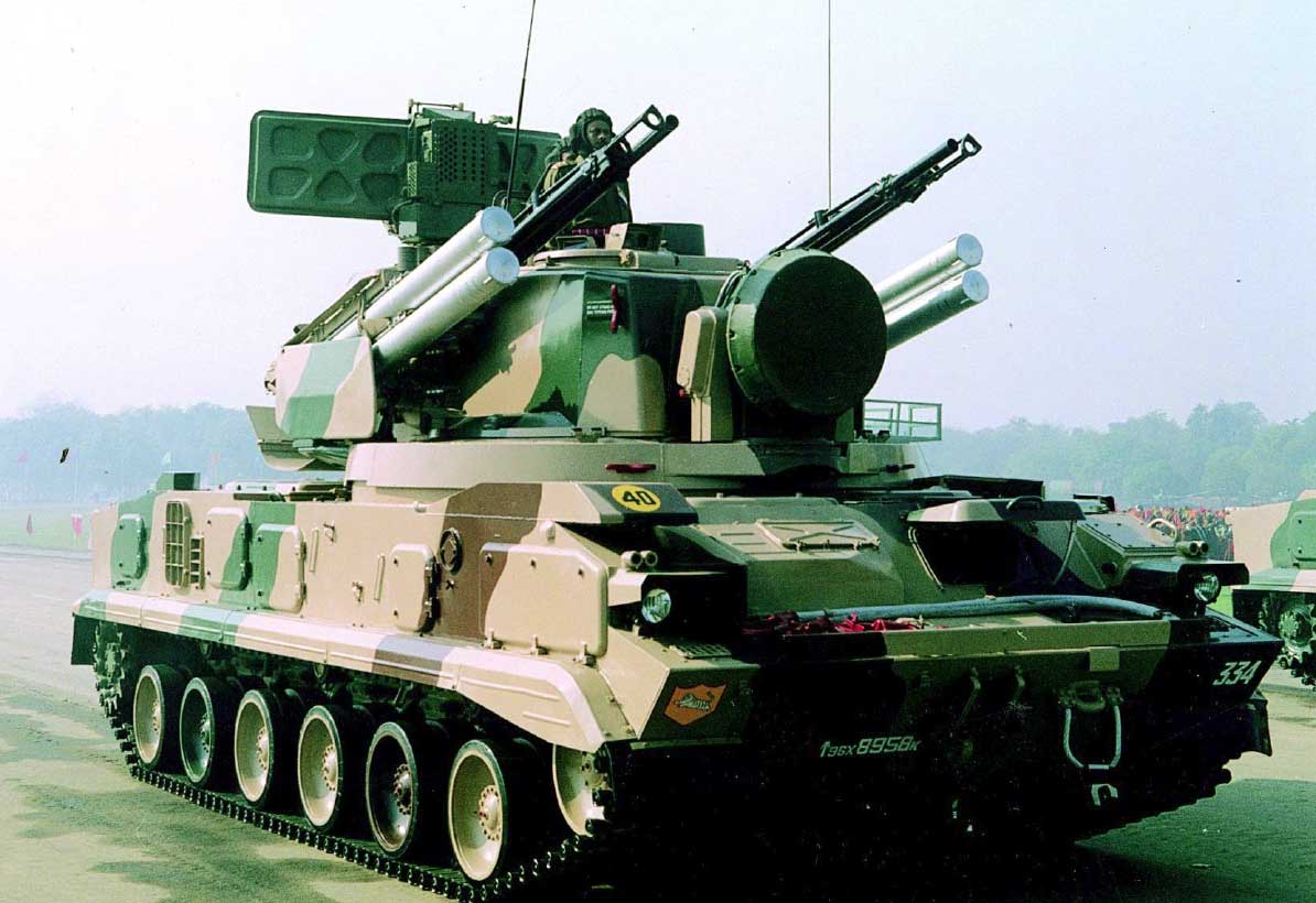
The Tunguska MRMS and its modifications are in service with the armed forces of Russia, Belarus. In 1999, Russia began supplying India with a total of 60 Tunguska-M1 SAM systems. Earlier India purchased 20 Tunguska complexes. According to some sources, the complex was delivered to Great Britain in the middle of 90s through GC "Voentech".
In the west, the complex was designated SA-19 "Grison".
Composition:
The 2K22 antiaircraft cannon and missile system consists of combat vehicles, maintenance facilities and training facilities located in 1R10-1 and 2B110-1 products.
The 2K22 SAM system combat vehicles include a battery of 2S6 self-propelled antiaircraft guns consisting of six combat vehicles.
Maintenance facilities of the 2K22 SAM system include a battery of 2S6 self-propelled air defence systems:
- 1P10-1 repair and maintenance machine,
- maintenance machine 2B110-1,
- repair and maintenance machine 2F55-1,
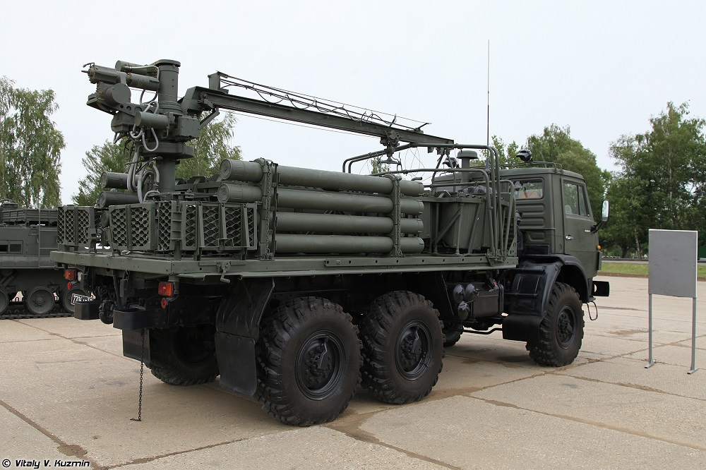
- 2F77M transport and charging machines (see photo),
- diesel power station ESD2-12,
- The workshop MTO-AG-1M (for maintenance of tracked chassis ZSU 2C6), automated monitoring and testing mobile station AKIPS 9B921 (for maintenance of missiles 9M311) are also involved in the maintenance.
The teaching and training aids consist of:
- training device 1PL912, designed for training and training the commander of the SSD and the operator,
- simulator 9F810, designed to teach and train the gunner ZSU.
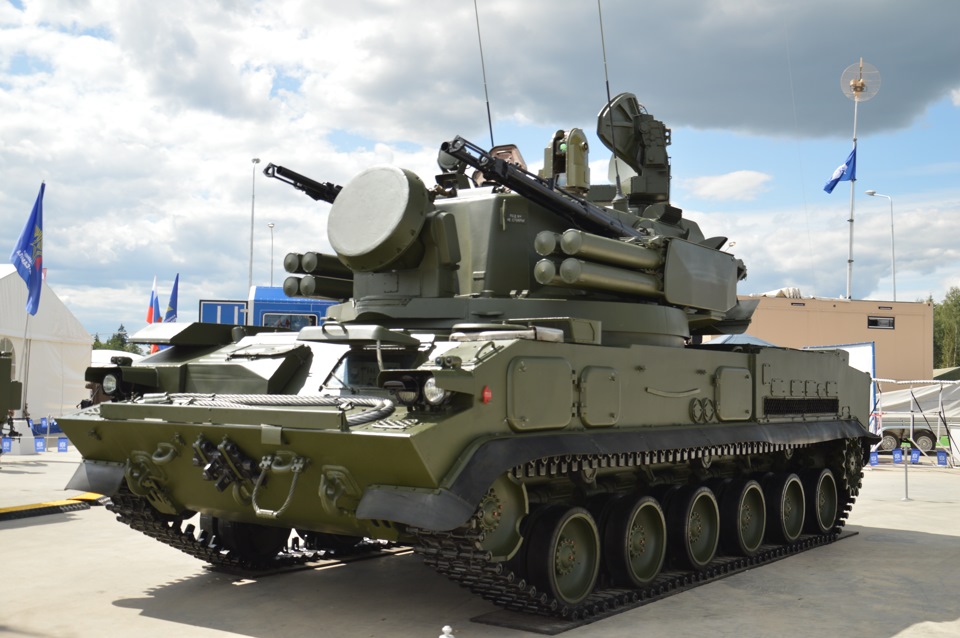
Self-propelled air defense system ZSU 2C6 consists of a tracked chassis GM 352, on which the tower 2A40 is installed. The tower is equipped with 1A27 RCK radio system, which includes 1PL144 radar system (see description), 1A26 digital computing system and 1G30 rocking angle measuring system.
Besides, the tower is equipped with an optical sight with 1A29 guidance and stabilization system, navigation equipment, external and internal communication equipment including R-173 radio station and 1B116 internal telephone communication equipment, means of protection against weapons of mass destruction, firefighting equipment, part of which is installed in the GM-352 tracked chassis, surveillance equipment, ventilation and microclimate system. The armored case protects the equipment and the calculation of the SSD from being hit by 7.62 mm caliber bullets and fragments.
Outside the tower, in its front part there is an antenna column of the target tracking station, from the outside on the sides of the hull of the tower are rails for the installation of missiles 9M311 (see description, projections) and anti-aircraft guns 2A38. On the roof of the tower, aft of the tower, there is an antenna column of the detection and target designation station.
The inner part of the tower, according to the location and purpose of the equipment, is divided into a control, artillery and aft compartments. The control department is located in the front part of the tower, the artillery compartment occupies the volume around the perimeter of the tower and the middle part of the tower cowl.
Interaction of the SSD components is shown in the figure.
To ensure combat operation of SSDs, the 1A27 instrument complex performs the following operations:
- searching for, locating and escorting air targets;
- issuing guidance signals to anti-aircraft guns;
- giving out missile control signals;
- generation of the current coordinates of the air defense system relative to the reference point;
- provides indication on the remote control of the commander of the SSD of the radar system operating modes.
Optical sight with guidance and stabilization system provides search, detection, tracking of air and ground targets and determination of mismatch between the missile position and optical sighting line of sight of optical equipment. The telescope sight with guidance and stabilization system consists of a guidance and stabilization system for the telescope sight, telescope equipment and coordinate equipment.
The sighting system is operated by SNS OP drives on control signals, received from the gunner's console or from the DAC.
External and internal communication facilities provide communication with an external subscriber and between calculation numbers.
The 2A40 tower is mounted on a tracked chassis. By appointment of systems and equipment the chassis is divided into a control department, a department for tower installation, a motor-transmission department and compartments for distribution of life support means, firefighting equipment, a power following drive of horizontal guidance, gas-turbine engine.
Power supply to the SSD is provided by the power supply system. The source of electric power of a direct current is the generator of a direct current which rotor is driven in rotation from GTE or from the traction engine. The converter unit converts direct current electricity into three-phase alternating current with a frequency of 400 Hz 220 V, designed to power the equipment of SSD.
The power tracking drive (PPS) of horizontal guidance is designed for automated guidance and stabilization of the tower according to the signals of CPSU and semi-automatic guidance according to the signals of SNS OP.
The PSC is an electrohydraulic automatic control system.
Repair and Maintenance Machine (MRTO) 1P10-1. MRTO 1P10-1 includes special control and verification equipment, radio measuring devices, communication facilities, primary power supplies, equipment ensuring normal operation of the product and its microclimate, means of PAZ, PCZ, PBZ, auxiliary equipment.
MRTO 1P10-1 is intended for maintenance of TS-1 and TS-2 and restoration of operability of electric and radio equipment ZSU 2C6 by replacement of defective components with serviceable ones from the group set ZIP ZSU 2C6.
MRTO 1P10-1 provides:
- carrying out technical maintenance of products 1PL144, 1A26, 1A29, 2E29VM, 1G30, block Sh1;
- restoration of serviceability of 1РЛ144, 1А26, 1А29, 2Э29ВН, 2Э29ГН, 1Г30 products, electrical equipment of 2А40 products and Ш1 block by replacement of defective blocks, sub-blocks and elements of hinged mounting by serviceable from the group set of ZIP ZSU;
- performance monitoring, checking and adjustment of separate blocks and systems included in 2C6 SCA.
- transportation of 1PL912 training device.
Maintenance Machine (MTO) 2B110-1. The MTO includes equipment, tools and materials used in carrying out maintenance and current repair of 2C6 and its components, R-173 radio station, telephone communication unit, CCW and PAZ devices, installation of primary power supply and means of life support and microclimate. The MTO is designed to perform technical maintenance of TO-1 and TO-2 and to restore serviceability of mechanical assembly units of 2C6 SSD, as well as for transportation of 9F810 simulator and gunner training at the rate of 2C6 SSD.
Repair and Maintenance Machine (MRTO) 2Ф55-1. MRTO 2F55-1 includes racks with cassettes, which contain spare parts from the group set of 2C6 products, separate components of single complexes of 2C6 products, monitoring devices and life support systems for calculation and creation of microclimate in the van body, PAZ and PCZ devices. MRTO 2F55-1 is designed to accommodate, store and transport a part of a group set of ZIP ZSU 2C6 as well as a part of the nomenclature of a single set of ZIP not placed on ZSU 2C6. ZIP elements are located in sliding drawers fixed in the frames along the sides of the van body.
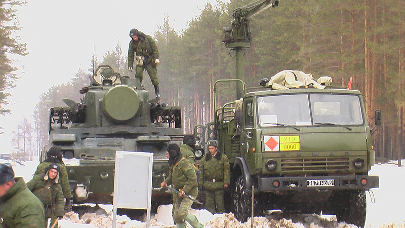
Transport Charger 2F77M . It consists of an electric crane, manazinas for placement of cartridge boxes, spools for laying missiles 9M311, machine for ammunition ribbons, radio P-173, PAZ and PCZ devices, devices for carrying boxes and night vision devices. It is designed for transportation of ammunition in boxes and a set of 9M311 missiles; self-discharging from the ground or vehicles; participation in charging, discharging and recharging of 2C6 SSD. One TZM 2F77M provides maintenance of two 2C6 ESUs.
Automated Control and Test Mobile Station (AKIPS) 9B921. It consists of special control and testing equipment for 9M311 missiles, standardized control and measuring devices, calculation life support equipment, electric installation of single-phase alternating current of 220 V 50 Hz.
The maintenance workshop MTO-AG-1M is designed for current repair and field maintenance of GM-352 tracked chassis and 2K22 vehicles. The workshop equipment allows to perform diagnostic, washing and cleaning, lubrication and filling works, adjustment of units, charging of storage batteries, tire repair, lifting and transporting, welding, carpentry and other routine repair works.
Diesel power plant ESD2-12 is designed for use as an external power supply source for SSD 2C6 during routine maintenance. ESD2-12 provides three-phase alternating current supply with frequency 400 Hz with voltage 220 V and direct current with voltage ±27 V (with average point).

2C6 SCA is mounted on the chassis of the multipurpose tracked heavy transporter MT-T. Hydromechanical transmission and hydropneumatic suspension with variable ground clearance provide high cross-country ability and smooth running on rough terrain.
Fire from 30 mm cannons 2A38 can be carried out on the move or from a place, and starting the ZUR only from a stop. The fire control system is radar-optical. The observation radar with a target detection range of 18 km is located at the rear of the tower. There is a target tracking radar with a range of 13 km in front of the tower. In addition to the radar, the fire control system includes a digital computer, a stabilized telescope sight and angle measuring equipment. The reaction time of the complex is 6-8s. The combat vehicle is equipped with a navigation system, top-positioning and orientation for determining coordinates. The unit is recharged from a special transport and charging vehicle on the chassis of KamAZ-43101 vehicle by container method. The recharging time of SSD by missiles and shells is 16 minutes. The hull and tower of the vehicle are made of all-welded armor and provide protection of the crew from bullets and fragments. The driver mechanic is placed in the front of the hull of the machine. The radar operator, commander and shooter are located in the tower.
The operation of the 2C6 combat vehicle was mainly autonomous, but the work in the air defense control system was not excluded.
The autonomous operation was ensured:
- target search (circular - using a detection station, sector - using a tracking station or telescope sight);
- Identification of the nationality of detected aircraft and helicopters using a built-in requestor;
- target tracking by angular coordinates (automatic - using a tracking station, semi-automatic - using an optical sight, inertial - using data from a digital computer system);
- target tracking by range (automatic or manual - with the help of tracking station, automatic - with the help of detection station, inertial - with the help of digital computer system, at the set speed, which was determined by the commander visually by the type chosen for target firing).
The combination of different methods of tracking the target by angular coordinates and range provided the following modes of operation of the combat vehicle:
- on three target coordinates obtained from the radar system;
- the range to the target obtained from the radar system and its angular coordinates obtained from the telescope sight;
- inertial tracking of the target at three coordinates obtained from the computer system;
- angular coordinates derived from the telescope sight and the target speed set by the commander.
When firing at ground moving targets, the mode of semi-automatic or manual aiming at a pre-determined point on the remote sighting grid was used. After search, detection and identification of the target, the escort station switched to its auto tracking on all coordinates.
When firing anti-aircraft guns digital computer system solved the problem of meeting the projectile with the purpose and determined the zone of destruction on the data coming from the output shafts of the antenna station escort, from the block of error signals on the angular coordinates and from a distance meter, as well as from the system of measuring the angles of rocking and course of the fighting vehicle. In the case of setting the enemy's intensive interference with the tracking station through the range measurement channel (autodalometer) was a transition to manual tracking of the target at a distance, and if it is impossible even manual tracking - to accompany the target at a distance from the detection station or its inertial tracking. When setting the intensive interference of the tracking station at angular coordinates, the target tracking along the azimuth and angle of the place was carried out with the optical sight, and in the absence of visibility - inertial (from a digital computer system).
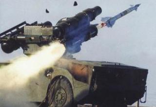
When firing missiles, target tracking at angular coordinates was used with the help of an optical sight. After the missile was launched, the ZRG fell into the field of view of the optical direction finder of the missile's coordinates selection equipment. Based on the light signal from the missile's tracker, the equipment produced angular coordinates of the LLS relative to the target sighting line, which were fed into the computer system. It generated the control commands of the SLCM, which were fed into the encoder, where they were encoded into impulse parcels and were transmitted to the missile via the transmitter of the tracking station. The missile's movement along almost the entire trajectory was 1.5 d. deviation from the target sighting line to reduce the probability of optical (thermal) trap hitting the target in the field of view of the direction finder. The missile's entry into the target sighting line started 2-3s before the target meeting and ended close to it. When the ZAR approaching the target at a distance of 1000 m, a radio command was transmitted to the missile to launch a non-contact sensor. When the time corresponding to the missile's 1000m flight from the target expired, the combat vehicle was automatically switched to the next SLCM ready to launch on target. If the computer system did not have information on the distance to the target from the tracking or detection stations, an additional mode of directional control of the SAM was used, in which the missile was immediately brought to the line of sight of the target, the non-contact sensor was launched 3.2 seconds after the launch of the SAM, and the warhead was ready to launch the next missile after the time of flight of the missile to the maximum range.
Organizationally, 4 combat vehicles of the Tunguska complex were reduced to an anti-aircraft missile and artillery platoon of the anti-aircraft missile and artillery battery, consisting of a platoon of Arrow-10SV SAM system and a platoon of Tunguska complexes. The battery is part of the anti-aircraft division of the motorized rifle (tank) regiment. As a battery command post is used the control point PU-12M, which was connected with the command post of the commander of the anti-aircraft division - the head of the air defense regiment. The latter was the "Ovod-M-SV" (mobile reconnaissance and control point for SPRU-1) or its upgraded version, the "Assembly-M" (SPRU-1M). Later on, combat vehicles of the Tunguska complex were to be paired with the unified battery command post 9C737 "Rangzhir". When paired with the "Tunguska" complex with the PU-12M control commands and CC from the latter to combat vehicles were to be transmitted in voice through regular radio stations, and when paired with the commander 9C737 - with the codograms generated by data transmission equipment, which should have been equipped with these means. If the "Tunguska" complexes were to be controlled by a battery-powered command post, the air situation analysis and the selection of targets for firing at each complex should have been done at that post. In this case, orders and target designation should have been transmitted to the combat vehicles, and data on the status and results of the combat operations of the complex should have been transmitted from the complexes to the battery command post. It was intended that in the future the anti-aircraft missile system and the commander's air defence control of the regiment would be directly interfaced using a telecode data transmission line.
Upgrade
By the middle of 1990 the complex "Tunguska" was modernized and received the designation 2K22M "Tunguska-M". The main improvements to the complex were the introduction of new radio stations and a receiver for communication with the battery command post "Rangzhir". (PPU-12M) and the command post of PPU-1M (PPU-1), as well as replacement of the gas turbine engine of the power supply unit of the complex with a new one - with an increased service life (600 instead of 300 hours).
The Tunguska-M1 modification automates the ZUR guidance and information exchange processes with the battery command post. In the 9M311M missile, the laser non-contact target sensor was replaced by a radar one, which increased the probability of hitting ALSM missiles. A pulse lamp was installed instead of a track - the efficiency increased by 1.3-1.5 times, the range of the LLRS reached 10 km. Work is underway to replace the chassis GM-352 produced in Belarus on the developed Mytishchi software "Metrowagonmash" GM-5975.
In complex 2K22M1 "Tunguska-M1" (2003) a number of technical solutions were implemented, which allowed to expand its capabilities:
- The equipment for reception and implementation of automated external target designation was introduced into the SSD, which via radio channel interfaces with the battery command post, which made it possible to automatically distribute targets from the battery control unit "Rangzhir" between the SSDs of the battery and significantly increased the effectiveness of combat application in case of massed raid.
- The unloading schemes have been introduced, which made the gunner's work easier when escorting a moving air target with the telescope sight, which reduced escort errors (it is very important when firing a missile at a target, as the miss should not exceed 5 m).
- The coordinate system has been improved in connection with the application of a new type of missile, which, in addition to a continuous light source, is also equipped with a pulse. This innovation has significantly increased the interference immunity of the equipment and made it possible to hit targets with optical interference with a higher probability. The use of the new missile type has increased the range of the missile weapon to 10,000 m.
- The system for measuring rocking angles and course has been changed, which has significantly reduced the perturbation effects on gyroscopes, reduced the tilt and course measurement errors of SSDs, increased the stability of the control loop of anti-aircraft guns and thus increased the probability of hitting targets.
- The operating time of the missile elements was increased, which increased the firing range from 8 to 10 km, and a radar non-contact target sensor (NDC) with a circular antenna pattern and a range of up to 5 m was introduced, which ensured the engagement of small targets (such as ALSM cruise missile).
Upgrading of the optical sight control system, DEM and radar significantly simplifies the process of tracking the target by the gunner, while increasing the accuracy of tracking and reducing the dependence of the effectiveness of the optical channel combat application on the level of professional training of the gunner. Work is underway to further upgrade the 2S6M1 SCA. Introduction of a TV channel with an automatic gun ensures the availability of a passive target tracking channel and the full day accuracy of the missile weapon application.
On the whole, the combat effectiveness of the Tunguska-M1 system under conditions of interference is 1.3-1.5 times higher than that of the Tunguska-M system.
Characteristics:
| Crew, man. | 4 |
| Dimensions, m: - length - width - elevation with the radar up - downgraded radar |
7.93 0.46 4.021 3.356 |
| Weight of machine, tons | 36 |
| Range of detection of air targets, km | 16-18 |
| Escort range, km | 10 |
| The reaction time, s | 10 |
| Range of fire, km: - cannon - ZUR |
0.2-4 2.5-8 |
| Tilt range of fire, km: - cannon - ZUR |
up to 4 up to 8 |
| Height of the targets to be hit, km: - when firing guns - when firing a ZUR |
0-3 0.015-3.5 |
| Technical gun rate of fire, gunshot/min. | 4000-5000 |
| Initial projectile velocity, m/s | 960 |
| Maximum flight speed of the target being fired, m/s | 500 |
| Angle of vertical gunfire, deg: - minimum - maximum |
-10 +87 |
| Speed of travel, km/h | 65 |
| Battle set: - 30 mm shells - ZUR |
1904 8 |
Testing:

The complex proved itself well in combat operations, in particular, a significant number of TOS-2 and TOS-2A missiles were used during the combat operations in the Persian Gulf area in 1991. According to the estimates of the foreign press, one of the Marine Corps units destroyed 93 armored targets, while using 120 vehicles.
The modernization of this complex is currently in progress. The works are aimed at further increasing the combat efficiency of the MANPAD, reducing its mass and dimensional characteristics and the amount of equipment included in its composition.
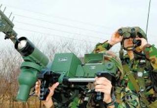
For example, a new ITAS launcher was developed on the instructions of the Ground Forces Command. Its main difference from the basic model is that all devices are combined into a compact unit, it uses a new combined sight, laser rangefinder and improved missile control equipment. Technical capabilities of the sight allow to engage targets in any visibility conditions at the maximum range of missile launch. In addition, it has advanced lifting and rotating mechanisms, as well as diagnostic and training equipment.
Raytheon has started to develop a missile capable of hitting targets on a "shot for forget" basis. It plans to develop a propulsion system using gel fuel, a more powerful BC, and a new thermal imaging homing head. At the same time, the missile should remain compatible with all TOW systems, including ITAS, and its launch range is expected to be at least 5 km.
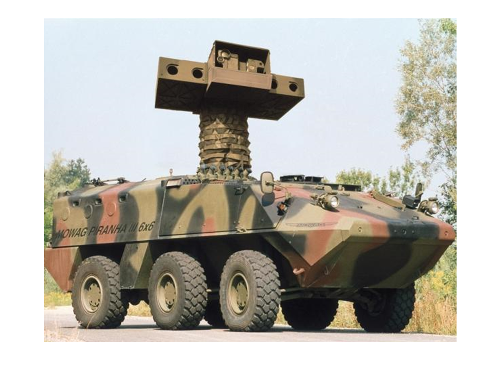
Modernization of TOS complexes is carried out in other countries as well. In Denmark, for example, ETS (Elevated Tow System) has been successfully tested to verify that ETS can be launched from behind a shelter. This system is capable of engaging armoured fixed and moving targets at a range of up to 4 km with TOP missiles of all modifications. ETS is a tracked armored vehicle M113A1 with a stabilized platform rising to a height of 7 m, which combines into a single compact unit optronic system and PU for four missiles in the armored body. The platform is elevated to the required height for reconnaissance purposes and for launching PTUR by means of a hydraulic drive from a camping position.
The optical-electronic system includes a combined sight with optical and thermal channels with a tracking system, a laser rangefinder and a unit of the missile's flight control equipment. In addition, the advanced lifting and turning mechanisms of the PU ensure that the platform turns in two-speed mode. All incoming information is displayed on the displays of the commander and gunner-operator of the complex, located at workstations inside the APC. This complex is capable of carrying 20 missiles, four of which are in the AP platform. Recharge of missiles can be carried out in automatic and manual modes.
According to the developers, the installation of the platform with a lifting mechanism is also possible for other types of combat vehicles, in particular, the LAV series.
Sources:
- Зенитный пушечно-ракетный комплекс 2К22. Техническое описание и инструкция по эксплуатации 2К22.00.000 ТО., 1989 г. - С.4,5.
- Зенитные ракетные комплексы ПВО СВ. Техника и вооружения №5-6.99
- "ТУНГУСКА" СТАНОВИТСЯ ЭФФЕКТИВНЕЕ. Военный Парад №33, 1999
- 2S6M Tunguska Anti-Aircraft Artillery
- Некоторые отечественные ЗРК
- ЗЕНИТНЫЙ РАКЕТНО-ПУШЕЧНЫЙ КОМПЛЕКС 2К22 "ТУНГУСКА" (SA-19 Grison)
- Russian/SovietPoint Defence Weapons
- Денис Мокрушин '6-я танковая бригада. Техника и подготовка'