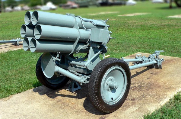
In the late 30's, German engineer Nebel designed a 150mm rocket projectile and a six-barrel tube launcher, which was named the 150mm type "d" smoke mortar. The mortar tests were started in 1937.
In 1941 the mortar was renamed to 150 mm Nb.W 41 (Nebelwerfer), i.e. 150 mm smoke mortar of sample 41. Naturally, the main purpose of "smoke mortars" was not staging smoke screens, but firing of rockets filled with toxic substances.
The Nb.W 41 rocket launchers entered the service of separate divisions and then the regiments of the so-called smoke troops (Nebeltruppen). Officially, the troops were intended to set up smoke screens, but their main purpose was to conduct chemical warfare. In order to ensure the possibility of using these troops in the war in case of chemical warfare as such, smoke troops were given to arm and fragmentation shells.
Interestingly, the Soviet soldiers called 150 mm Nb.W 41 "Vanyusha", similar to the M-13, called "Katyusha".
The "d" mortar was intended for quick and strong fire attack. Due to its high firepower, it was used in the main strike area in order to:
- Shrapnel mines to cause material destruction, to influence the enemy morally and to suppress life force.
- Chemical mines to achieve in the shortest possible time, a strong concentration of gases in the affected area.
- Create smoke screens in especially important moments of battle to blind observers and weaken the enemy's anti-tank defense.
The mortar, due to its inherent high dispersion, was not suitable for firing single targets and targets close to the line of its own troops. It was fired at squares, with a volley of 6 shots during 5 seconds. Prolonged firing from the same firing position was not allowed due to the last smokestack of the mine. For the same reason it was forbidden to shoot with the mortar "d" and from the very beginning it had a striking character. The method of firing for the battery was a firing attack.
The production of the Nb.W 41:
- 1940 - 282 pcs.
- 1941 - 652 pcs.
- 1942 - 969 pcs.
- 1943 - 1188 pcs.
- 1944 - 2336 pcs.
- 1945 - 342 pcs.
Total: 5769 pcs.
Composition:
The mortar consisted of the following main parts:
- the carriage,
- of a trunk bag,
- of the sighting device.
Lafette.
The main parts of the carriage (see diagram): lower machine with sliding bases and front stop, upper machine with guide mechanisms and wheels with crankshafts.
The lower machine with sliding bases (see diagram) is a box bent from sheet steel. Side walls, bearings, guides, ribs and fixtures are welded to it. The lower machine tool serves as a guide for the upper machine tool; it is supported by bases, podressorivanie, cranked axles and the front stop. On the upper part of the lower machine is welded a guide sector on which is placed the upper machine with guides. On the inner side of the guide sector there are teeth, which are meshed with a small drive pinion. To the left of the guide sector is a pointer to the middle position of the trunks; to the right is a hiking gear. The slide lock is located on the upper machine tool. There is also a sleeve for swivelling on the upper machine tool.
Mortar sliding bases are made of steel pipes (see photo), they consist of a fork with a sleeve, a pipe and a coulter. The forks are hinged in the lower machine, on the outside of the forks there is a bracket for securing the human traction strap, and on top of them there is a bolt with springs. When tilting the frame, the bolt jumps into the hole in the lower machine tool and fixes the frame in an extended position. When firing, the extended frames serve as the rear stop of the mortar. Both frames have grips for a detachable carriage box. On the coulter plates there is a mechanism for securing the frame in the hiking position. It consists of a connection mark and a locking lever. The connecting mark and locking lever for extended frames are secured by spring clips welded to each coulter plate. A finger welded to the side wall of the right coulter is used to relieve this mechanism from shocks during travel. It enters the opening of the side wall of the left coulter and absorbs the shocks during transport. The coulters are equipped with brackets, which are used to lift the beds during maintenance and during transport of mortars by the force of calculation. The coulters are also equipped with stubble brackets. In addition, each coulter is equipped with a shovel fixing bracket.
Springs and low-pressure pneumatics are used as suspension of the mortar during transport and to protect the material part from shocks. (Pressure in them 1.7 - 2.0 atmospheres). The pneumatic wheels are placed on the ends of the crank halves, which when the mortar is brought into the combat position turn and lift the wheels above the ground.
The front stop, located on the lower machine, serves as a stop for the system in the combat position. It consists of 2 pipes with welded hinges and a disc. A spring lock with a handle is mounted on the disc. On the side walls of the lower machine there are two rotating handles of the locking mechanism that fixes the rigid position of the front stop in the combat position.
The locking mechanism of the front stop (for combat position) consists of a roller, 2 handles, 2 forks, 2 lever forks and 2 spring-loaded fingers. The fingers are spring-activated in the corresponding sockets of the front stop hinges.
The upper machine is a welded sheet steel body. Shafts, swiveling and lifting mechanisms are located on it. In the middle of the upper machine is a bearing for the swivel (vertical trunnion). The rotation of the upper machine is carried out around this trunnion. The trunnion is lubricated through a pressure lubricator. A guideway is welded to the lower side of the upper machine tool and is adjacent to the guideway sector of the lower machine tool. For lubrication of the sliding surfaces of the upper and lower machine tools there are 3 oil jars. The swivel mechanism to protect it from contamination is completely closed; it consists of: bearing bushing, worm shaft with worm and handwheel, worm gear with small drive pinion, gear sector and box cover. Lifting gear consists of: worm shaft with worm and flywheel, worm shaft with small drive pinion, gear sector and box cover. The lifting gear is also closed, except for the small drive pinion, which is meshed to the toothed sector and screwed to the lower barrels. Pressure oilers are used to lubricate the guidance mechanisms. The worms and worm gear boxes are covered by caps. Lifting and swinging mechanisms are self-locking, i.e. once installed, they are not knocked down without fastening at gunshot. On the left side of the upper machine there is an indicator of its middle position.
The studded sockets on the upper machine tool brackets are used to locate the trunks; they are lubricated with one pressure lubricator each. At the rear on the right side of the upper machine is its travel mount, consisting of a lever with a catch.
The trunk package
The bag of guns included: Translated with www.DeepL.com/Translator (free version)
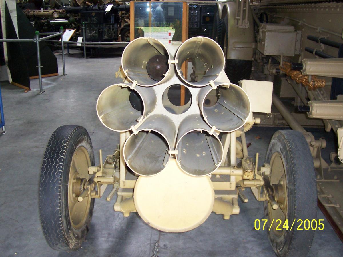
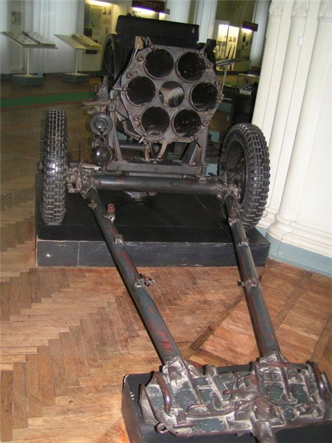
- 6 steel barrels connected by two (front and rear) clips. The rear part of the barrels had mine action grips and extractable spring contacts.
- Dividing plug-in box with lid.
- Angle pad (on top of the barrels).
- Lifting gear toothed sector.
- Inflow with opening for front stop lock (bottom at muzzle part).
- Right and left trunnions.
The barrels are mounted in the front and rear cages at the corners of the hexagon. Each barrel is individually mounted at the corners of the barrels, so any barrel can be changed separately. Inside the barrel, 3 strips, 1300 mm long, are screwed on an equidistant distance around the circumference of the barrel, on which the mine slides. The diameter between the strips is 158.5+0.4 mm. The strips are designed to reduce the friction force between the mine and the walls of the barrel channel.
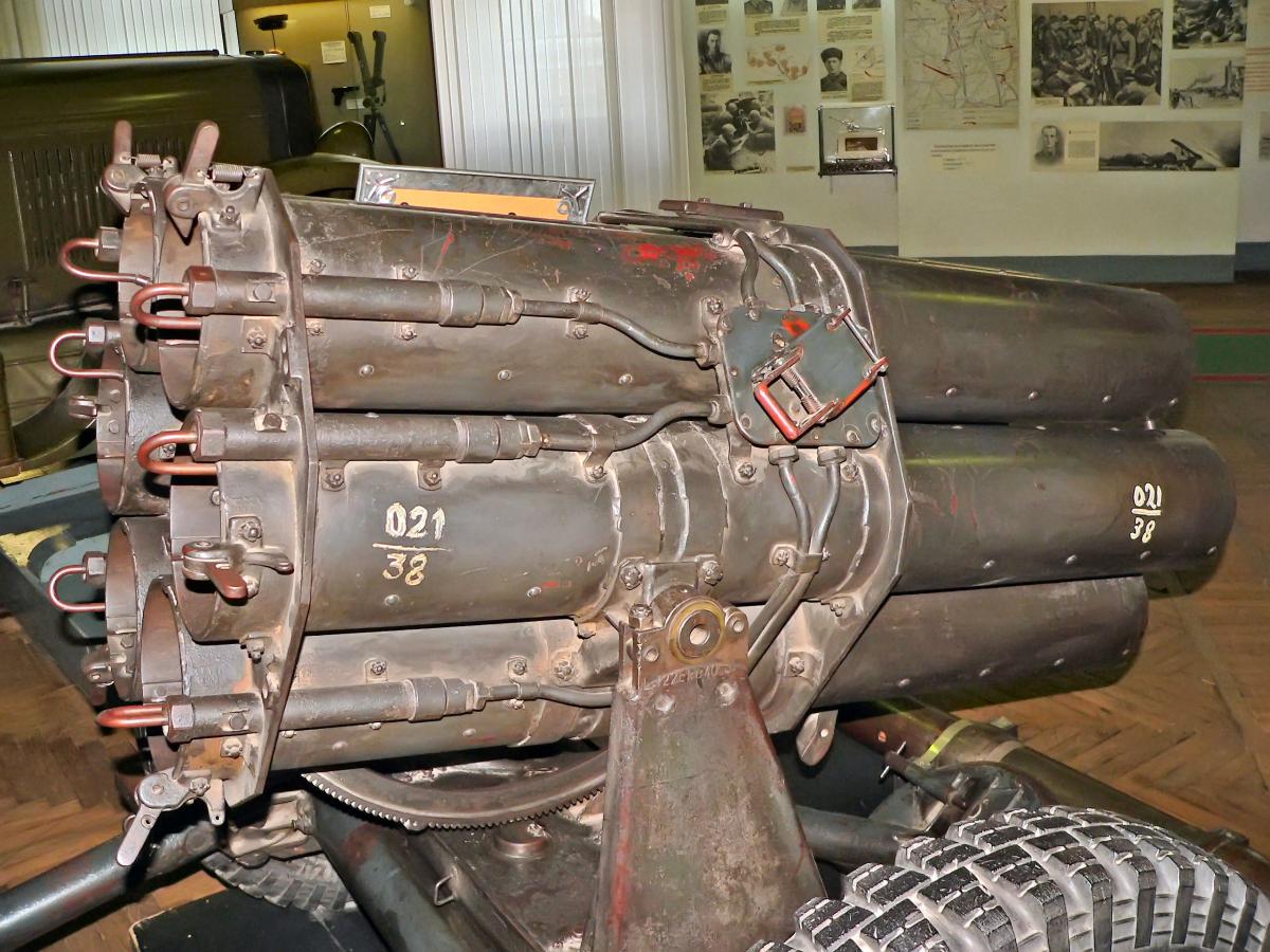
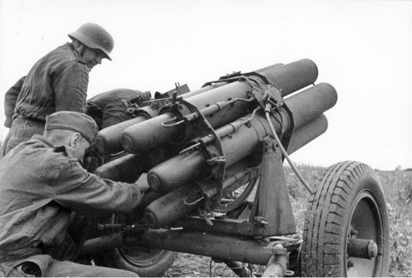
The trunk channel axes are mutually parallel. Each barrel has a hood at the rear of the barrel that contains a spring contact and a spring clamp that serves as a stop for the mine (see photo). When the mine is pushed from the breech ring into the barrel, the stop retracts, and when the mine is parked, the stop prevents the mine from slipping out of the barrel by jumping behind the turbine.
From the hood, the barrel is fitted with a waterproof steel tube with electrical wiring to the contact box. The contact box has 7 plugs. The middle plug is connected to the mortar and is the common pole. The remaining 6 plugs are insulated in relation to the system and are connected to the spring contacts by an electrical line. At the top of the front ring there is a goniometer platform covered with a screw cap. Between the two lower barrels there is a toothed sector of the lifting mechanism at the bottom, and closer to the muzzle there is an inflow for the front stop lock. Left piston is fitted with sighting mechanism and protector box of the quadrant.
Sighting device
The sighting device includes: angled quadrant, aiming mechanism and extension bracket.
Anglo-meter-Quadrant (KA-35 or KA-38). The Quadrant is installed on the rack above the sighting mechanism on the left side of the mortar. In contrast to the conventional division of the angular scope into 6000 small divisions adopted in the Red Army, the German sights have the angular scope circle broken into 6400 divisions. When changing the direction by one small division of the anglomer, the lateral deviation in both cases is about 1/1000 of range. The direction of reference of the angle gauge scale of the German sights was taken backwards in comparison with the Red Army sights. The Quadrant Anglomer is protected from contamination when firing a protective box or is removed from the mortar. During transportation the goniometer is placed in a special case in the carriage box.
Horizontal mechanism of the sight. The mortar has no device to eliminate wheel distortion. For alignment of the angle gauge circle in a horizontal plane the mechanism of horizonation at the sight itself serves. The mortar should be mounted horizontally, if possible, to avoid significant lateral deflection when the mortar is fired. The horizon-type mechanism of the sight is used only for elimination of slight misalignment (up to 2°=36 of the sights division).
Extension bracket. Extension bracket serves to raise the quad above the barrels for easy aiming. It is made of light metal. There is a swallow's nest on one end of the bracket, and a swallow's tail on the other.
Accessories (ZIP)
Accessories include:
- Lafette box, which contains: electric ignition machine, cable drum (30m seven-core electric cable), angle meter-quadrant in a case, extension bracket of the quadrant, 4 straps, 4 constructions, 2 bags, lighting for the quadrant, key for the bottom fuse and the form of the trunk and the carriage;
- lubricated box with spare parts, containing: accessories for discharge lubrication, spare parts (12 lugs for spring contacts, pressure screw spring, 6 grippers to hold min, 12 tension springs), hammer, pliers. In the same box there are: for each platoon one "35" angle meter and one angle meter, and for each battery one ignition device and one electric ignition machine.
The electric cable consists of 7 mutually insulated conductors. At one end it has a plug for 7 contacts and steel armour 2 m long, and at the other end it has a plug for connection to an electric ignition machine. One of the cable drums is located in the carriage drawer, the other (spare) is on the car.
Electric ignition machine is a dynamoelectric mechanism with manual drive, which makes it possible to ignite the fuses of mines in a sequence of barrel numbers: 1 - 4 - 6 - 3 - 5 - 2. The cover of the electric ignition machine has a hole to observe the order of numbers determining the inclusion of the barrels, 7 sockets and a pin, on which the detachable handle is put on. The handle of the igniter is put on the trunnion only at the command "Fire".
| In the ignition position. | 1 | 2 | 3 | 4 | 5 | 6 |
| Shoots the barrel. | 1 | 4 | 6 | 3 | 5 | 2 |
Ammunition
The mortar was fired from uncontrolled reactive mines (see description), stabilized in flight by rotation around the longitudinal axis. The mortar ammunition consisted of the following types of shots:
- shrapnel-and-foot,
- special (chemical, smoke)
- educational.
Special-purpose mines (chemical - see diagram and smoke - see diagram) differed from shrapnel-flash mines only by changing the internal structure of the hull and the location of explosive and special charges in it. In contrast to a shrapnel-flue mine, the hull of chemical and smoke mines had a welded turbine. A central tube was screwed into the chamber of the mine body, in which the detonator and the explosive charge were placed. A small or large central tube was used for these mines. The identification mark of the chemical mines was a coloured ring, painted with yellow paint on the head and on the body of the mine, while for the smokeboxes a green-yellow ring with the number 38 was used. TNT or tan was used as a bursting charge for chemical mines.
The head part of the jet mines is very similar to the head part of one of the rockets proposed by the Englishman V.Congressives (see photo).
The total ammunition consisted of 90 rounds (75% fragmentation and 25% smoke) for each mortar, with 36 rounds of them in the mortar. A set of chemical mortars was to be issued under a special order.
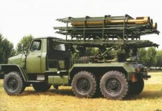
Transportation of the mortar could be carried out:
- on the trailer after the tractor;
- medium all-terrain trucks;
- human traction.
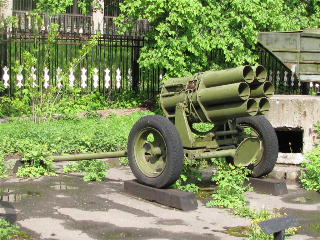
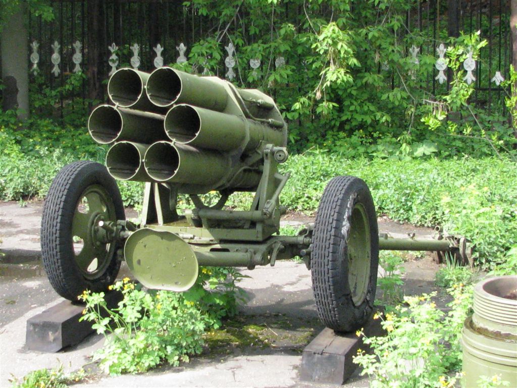
Look at the photos (©S.V. Gurov (Russia, Tula)) from the exposition of the Central Museum of the Armed Forces of the Russian Federation (Moscow, Russia): photo 1, photo 2, photo 3, photo 4.
Characteristics:
| Caliber, mm | 158,5 |
| Weight in combat and hiking position, kg | 510 |
| Maximum range of fire, m. | 6100 |
| Effective range of fire, m | 4000-6000 |
| Vertical firing angles | from -100 to +800 scope divisions |
| Horizontal firing angles | ±210 fission |
| Shrapnel shells and their markings | ||||
| Name of projectile | Shrapnel projectile with black powder charge from Schw brand | Shrapnel projectile with Digl.P. grade digl.P. gunpowder charge. | Shrapnel projectile with Digl.R. branded Digl.R. gunpowder charge. | Shrapnel projectile with Arkt arctic gunpowder charge |
| Caliber, mm | 158 | 158 | 158 | 158 |
| Weight of projectile, kg* | 38,33 | 34,15 | 34,15 | 34,15 |
| Weight of BB, kg | 2 | 2 | 2 | 2 |
| Rocket charge gunpowder | One solid checker | One 9-channel draughtsman | 12 tubular and 8 solid checkers | 7 pipe sticks |
| Fuse | Don Bd. Z. Dov. | Don Bd. Z. Dov. | Don Bd. Z. Dov. | Don Bd. Z. Dov. |
| Combat unit hull marking | Weight mark* | Weight mark* | Weight mark* | Weight mark* |
| Camera Marking | Schw | Digl. P. | Digl. R. | Arkt |
| Muzzle painting | - | - | - | White Paint |
| Marking the capping | Mun. Beh. 4644 | Mun. Beh. 4644 | Mun. Beh. 4644 | Mun. Beh. 4644 |
| Painting the capping | The lid has a pink stripe | The lid has a pink stripe | The lid has a pink stripe | The lid has a pink stripe |
| Temperature limits at which firing is permissible |
from -40° up to +40° |
from -25° up to +25° |
from -25° up to +40° |
from -40° up to +10° |
| firing table number for this projectile | № 1 | № 2 | № 2 | № 2 |
| Smoke projectiles and their marking | ||||
| Name of projectile | Smoke projectile with black powder charge from Schw brand | Smoke projectile with Digl.P. Digl.P. powder charge. | Smoke projectile with Digl.R. Digl.R. Digl. | Smoke projectile with arctic powder Arkt charge |
| Caliber, mm | 158 | 158 | 158 | 158 |
| Weight of projectile, kg* | 39,66 | 35,48 | 35,48 | 35,48 |
| Weight of BB, kg | 1,3 | 1,3 | 1,3 | 1,3 |
| Порох пороха для заряжания ракеты | One solid checker | One 9-channel draughtsman | 12 tubular and 8 solid checkers | 7 pipe sticks |
| Fuse | Don Bd. Z. Dov. | Don Bd. Z. Dov. | Don Bd. Z. Dov. | Don Bd. Z. Dov. |
| Ballistic tip marking | White ring and numbers 38 | White ring and numbers 38 | White ring and numbers 38 | White ring and numbers 38 |
| Combat unit hull marking | Nb–38 and the weight mark | Nb–38 and the weight mark | Nb–38 and the weight mark | Nb–38 and the weight mark |
| Camera Marking | Schw | Digl. P. | Digl. R. | Arkt |
| Muzzle painting | – | – | – | White Paint |
| Marking the capping | Mun. Beh. 4644 | Mun. Beh. 4644 | Mun. Beh. 4644 | Mun. Beh. 4644 |
| Painting the capping | The lid has a pink stripe | The lid has a pink stripe | The lid has a pink stripe | The lid has a pink stripe |
| Temperature limits at which firing is permissible |
from -40° up to +40° |
from -25° up to +25° |
from -25° up to +40° |
from -40° up to +10° |
| firing table number for this projectile | № 4 | № 5 | № 5 | № 3 |
* By weight, German rockets were divided into three classes: low weight (with sign I), normal weight (with sign II) and high weight (with sign III). The weight mark was painted on the projectile body near the turbocharger.
Look on a theme on our site: Rocket technique in an exposition of the Military Historical museum of artillery, engineering and communication armies (St.-Petersburg). Part I.
Testing:
The Certificate of Combat Activity of the 15 mortar regiment of the 33 minbrigade 2 gv of the Art division of the Russian State Control Committee for the period from 13.07.43 to 20.10.43 states that "since the beginning of combat operations, the regiment has destroyed ... 6 barrel machine guns - 1" (presumably, we are talking about the 6 barrel mortar).
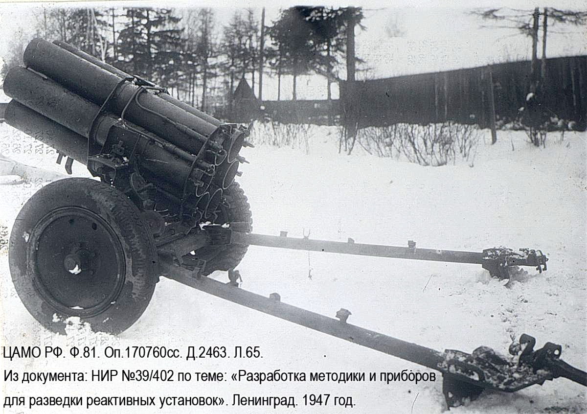
Among the targets, which were found by the soldiers of the 15th mortar order of Alexander Nevsky regiment, was the mortar "d". The description of the targets indicates: PP-690 SP groups as of 05.02.44.
No. of the targets 286; Coordinates x 09500; y 56925; Name of the targets Mortar "d" / rolling; Date of detection 27.01.44; Who is assigned 1/15; Who was detected 2/12; Chief of Staff Captain Tabunshchikov
The Report on the enemy artillery activity in the area of the 15 mortar regiment of the 33 min brigade from 25.01.44 to 24.02.44 Perekop. indicates "the enemy, consisting of 71 demining battalions, 122 pp, 121 pp 50 pp, and a battalion of traitors of the Motherland occupies the defense at the turn: exclusive collective farm named after Budyonny, estate 200 m southeast of the brick factory, exclusive height 19.6. Barrows with an exception of 0.8 d Shchemilovka.... 2. The enemy's artillery is mainly concentrated: ...up to two 119 mm batteries and a mini "d" battery in the area of 17.3" height.
Vitaly Zakrutkin's book "Caucasian notes 1942-1943" contains the following data: "Together with large motorized units, along the Don and Kuban roads there were separate "shock" and assault regiments, detachments of automatic rifles, sapper, technical, bicycle battalions, airborne groups, security units, companies of field gendarmerie, all kinds of "volunteer legions", assembled from reputed adventurers of different nations; the infinite flow of heavy and light cannons, the divisions of six-barreled mortars. ».
V. Zakrutkin's book "Caucasian notes 1942-1943" also contains data on the seizure of 4 six-barreled mortars by Soviet troops on the outskirts of the town of Ordzhonikidze (now Vladikavkaz).
Sources:
- Таблицы стрельбы 158-мм немецкого реактивного миномета. Осколочные снаряды. Дымовые снаряды. Выпуск №9. Народный комиссариат обороны. Захваченное оружие поверни против врага. М.: Воениздат НКО, 1944. - С.6-9.
- Германский шестиствольный миномет "d". Главное артиллерийское управление Красной Армии. - Артакадемия. - 1942 год. - С.3-57.
- ЦАМО РФ. Ф. 81. Оп. 170760сс. Д. 2463. Л. 65.
- ЦАМО РФ. Ф. 15 миномётный Ордена Александра Невского полк. Оп. 920696. Д.1. Л. 27,27об,31,100.
- Авторские фотографии (©С.В. Гуров (Россия, г.Тула) видов миномёта - трофея Красной Армии - из экспозиции Центрального Музея Вооружённых Сил Российской Федерации (Россия, г.Москва).
- 'Ванюша' - противник и соратник 'Катюши'
- ПАМЯТКА О РЕАКТИВНЫХ СИСТЕМАХ АРТИЛЛЕРИИ Германской АРМИИ. Документ без подписей и мест для них // ЦАМО РФ. Ф. 21 ОГМД. Оп. 16691с. Д. 7. Л. 7-9. / Приложение к письму из 2-й ОПЕРАТИВНОЙ ГРУППЫ Гвардейских минометных частей ”.....“ армии Западного фронта 21 Марта 1942г. № 600 от Нач.штаба 2-й Опергруппы Гвард.Миномеьи.частей капитан Франченко (расписался другой человек через косую черту) КОМАНДИРАМ ДИВИЗИОНОВ // ЦАМО РФ. Ф. 21 ОГМД. Оп. 16691с. Д. 7. Л. 6.
- 150-мм шестиствольный реактивный миномет Nb.W. 41
- VOJENSKÉ RAKETY. Jiřί Kroulik • Bedřich Růžička. NAŠE VOJSKO • PRAHA.
- Закруткин В. Кавказские записки 1942-1943. – М.: Советский Писатель, 1954. – С. 18,308.
- Владикавказ. [Электронный ресурс]. Дата обновления: 24.11.2017 г. // URL: https://ru.wikipedia.org/wiki/Владикавказ Дата обращения: 03.12.2017 г.
