
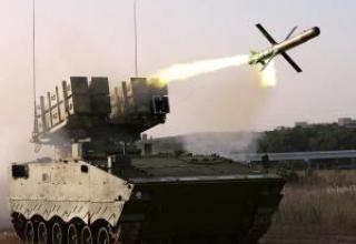
Aerospatiale (France) and MBB (Germany) are jointly exploring the possibility of equipping submarines with an anti-aircraft missile system capable of hitting the depths of anti-submarine helicopters and maritime patrol aircraft. Many warships now have anti-submarine helicopters on board, which, along with aircraft, are the most serious threat to submarines. Possessing weapons, the submarines will not remain passive against this threat, and anti-submarine aviation will no longer be immune to them. This will change the basic rules of submarine warfare.
For this purpose, the development companies intend to use the anti-tank and anti-submarine missile system Polypheme, which they are currently developing, with the guidance of the missile using a fiber optic communication line. The missile for the Polypheme complex, respectively, is being developed in two modifications. The submarine antiaircraft missile is based on the antiaircraft version. However, unlike it, instead of the standard TV camera, the Polypheme-SM missile will receive a thermal imaging camera, which will allow the submarine to fight against aircraft in any submarine.
time of day and in any weather, including even in shallow rain with visibility up to 4 km.
The rocket is enclosed in a strong waterproof capsule with a diameter of 240 mm, a length of 1.95 m. and a weight of 105 kg, thrown out of the submarine with compressed air, equipped with its own engine and coil with a fiber optic cable to move underwater. The engine runs for about one second, allowing the capsule to pass under water at a speed of 15m/c distance up to 900m. When the capsule reaches the surface, it opens longitudinally split into two halves and releases the rocket, which in turn opens the plumage - cross wings and rudders, starts the starting engine and turns on the thermal imaging camera.
After leaving the water, the missile will describe a spiral at a low speed of 150 m/s, allowing the submarine operator to evaluate the tactical situation in the air and select a target. Once a target is selected, it is captured by the homing system, the marching engine is engaged and the missile is automatically launched.
is heading towards the target at a speed of 259 m/sec. In doing so, the operator maintains the ability to identify the target and intervene in the homing process.
The missile can be launched from a submarine at a speed of up to 50 knots (92.5 km/hour) both from periscope immersion and from depths up to 300 m. (according to other information up to 900m.) The adopted layout of the missile provides a range of 10 km, and an obstacle to increase the range is only the dimensions of the capsule on board the submarine. However, the method of guidance with bi-directional transmission of signals over fiber optics - images from the missile to the launcher and the command to control back to the missile - in principle, allows you to increase the range of the missile, respectively, up to 60 km and 350 m/s.
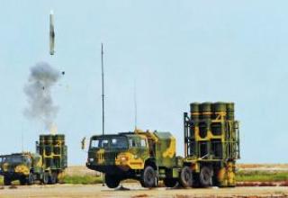
The concepts of Aerospatiale and MoHV differ only in the way the missile is stored and launched. The West German Navy prefers the MBV concept, which provides for the launch of missiles from the tubes of a torpedo. In this case, the missile is first removed from the boat under water before appearing on the surface to attack the target, so as not to detect the exact location of the boat, usually operating in shallow depths of the North or Baltic seas. On the other hand, the French navy, which has a different understanding of the use of its submarines operating most often in the open sea, is likely to choose the concept of Aerospatiale, which involves the sparing of a capsule with a rocket of vertically-mounted launch mines mounted on a submarine.
The launch of the Polypheme-SM missile could also be used by the commander of the submarine to clarify the tactical situation at sea, allowing the detection of high-priority targets, which would then be attacked by torpedoes or PCR of the submarine launch Exocet.
Composition:

The Polaris-A3TK ballistic missile inherited the main design features of its prototype, the Polaris-A3T SLBM. The missile was made of two stages with sequential connection of steps, whose bodies were made of fiberglass by winding the fiberglass with epoxy glueing. Within the framework of a special program carried out since 1981, the first marching stage of the Polaris-A3TK SLBM with the RDT A3P developed by Aerojet General was modified - the insert was replaced, new solid fuel was poured instead of the old one, a number of units were replaced, and measures were taken to increase the stability of the stage against PFC. All Polaris-A3TK missiles were modified as part of this programme during 1986-1987. The first stage RDTT march rocket had four rotary nozzles. The nozzles were made of aluminium alloy with special coatings. To control the engine thrust vector on the first stage of the rocket used ring deflectors, mounted on each of the nozzles and articulated with the appropriate hydraulic drives. Tests have shown the high efficiency of this type of steering device and, in particular, the possibility of taking the missile to the trajectory even with a significant vertical deflection at the moment of switching on the first stage engine. The control system made it possible to control the missile through pitch, yaw and roll channels. The engine was powered by an electromechanical device and a powerful fuse, while the tail plugs of the nozzles, which protected the engine from water ingress during the underwater course of the missile, were pushed out by the working gas pressure at the moment of engine activation.
On the second stage rocket engine X-260, developed by the company "Hercules Powder" four fixed nozzles. Control forces were created by injecting freon into the critical part of the nozzles. Stock of CFC was stored in a toroidal tank, which was filled at factory conditions. This system made it possible to control the rocket through pitch and yaw channels. The second stage of the Polaris-A3TK was also modified. The set of measures taken was approximately the same as for the first marching step. The steps were connected by means of an aluminium alloy adapter. For division of marching steps the fire way was used. In a forward part of the adapter the charge which worked at the moment of division was fixed.
The control system equipment is located in the nonseparable instrument compartment which is in a forward part of the case of the second marching step of a rocket. It housed a platform with accelerometers and a block of high-speed gyroscopes, flight control software, a block of auxiliary electrical equipment, BCVM, power supplies, etc. In the course of the Chevaline program, the control system hardware was significantly modified, first of all, to improve the accuracy of firing and to increase the resistance to fossil fuels. Due to the application of the new element base, it was possible to reduce the weight of the system. The results obtained during the extensive R-1 research project on this topic were widely used to improve the stability of the Chevaline BC and BC systems against PFCs.
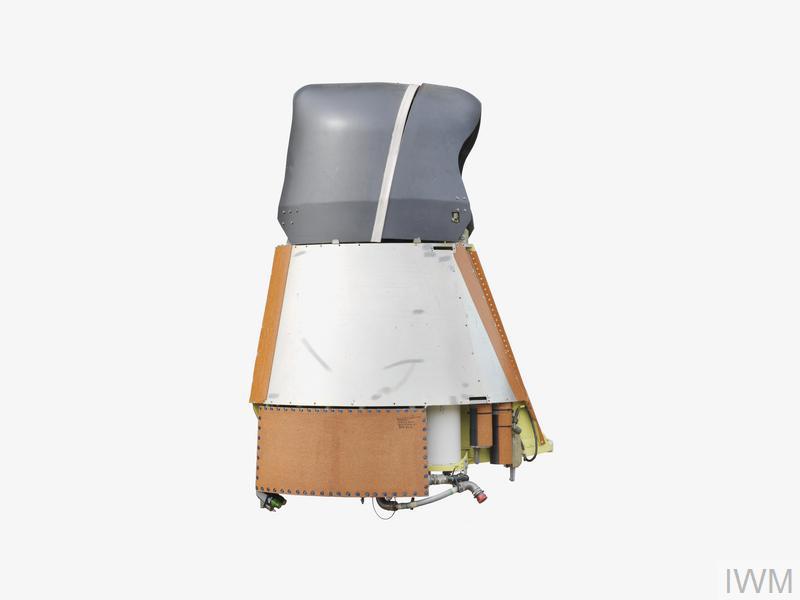
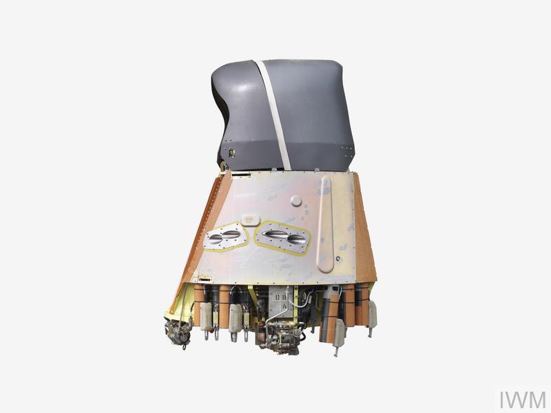
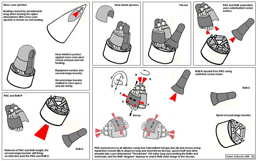
The most interesting part of the project "Chevaline" became the head part with a breeding stage - simply because the degree of originality (often simply inexplicable) embedded in it technical solutions, as far as we know, this system had no analogues in the world. The breeding stage (see Scheme-1, Scheme-2, Scheme-3, Scheme-4) was made of aluminium alloys with inclusion in especially responsible places of steel details. Most of the surface of the breeding stage outside had a special heat protection coating to reduce the thermal loads from small head cowling RDTT at the time of its removal. The nose part of the stage, which had the main thermodynamic loads at the moment of head cowling removal, was covered with a heat shield made of organic materials, which was fired off a few seconds after the head cowling was removed. Breeding stage had its own electronic control unit "Electronic Control Assembly" (ECA), which provided: the process of initiation of the breeding stage systems and the MS, the issuance of commands to the propulsion system to orientate the stage in space, power supply to all systems of the stage, and so on. The unit included a power supply unit on thermopile (duration of operation up to 9 minutes with the possibility of extension up to 20 minutes), BCVM control system of the breeding stage (which was made on radiation-resistant electronics EEPROM-type) and a set of auxiliary equipment. All systems of the unit were placed in a housing made of titanium alloy and were shielded from PTFE. The breeding stage was equipped with the "Space Reference Unit" (SRU), which consisted of a complex of gyroscopes and accelerometers. The unit provided the BCVM with data on angular deviations of the breeding stage and accelerations.
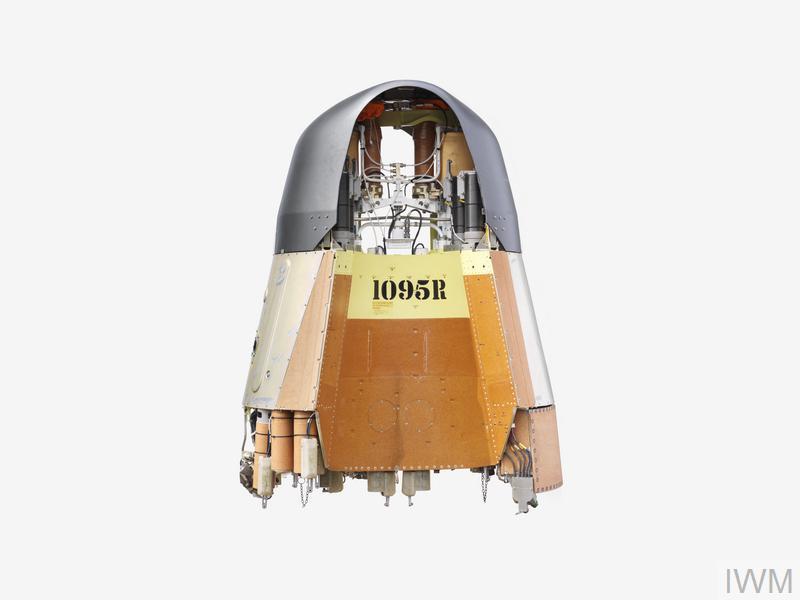
An important part of the breeding stage was the "Bus Propulsion Unit" (BPU). The unit consisted of a liquid marching engine running on highly boiling self-ignition fuel components (inhibited red smoky nitric acid IRFNA as an oxidizer and hydrazine MAF-1 as a fuel). The average engine draught is 6.3 kN, full impulse is 77.5 kN. Fuel consumption - 2.5 kg/s. BPU provided change of speed of a dilution stage by an amount up to 200m/s with an accuracy of 0,1m/s. The displacement of fuel components from the tanks was due to the excessive pressure of nitrogen injected into the tanks. The engine had a system of two uncontrollable nozzles, which could operate alternately or simultaneously. Working together with two packs of solid fuel gas generators of different power (each generator had a block of four nozzles), this power plant provided the orientation of the stage of dilution in space and provided the construction of combat orders of the BC and CSP anti-missile defense with sufficient accuracy (see Figure 1, Figure 2).
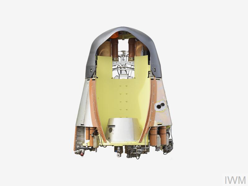
For separation of a step of cultivation from the second marching step two solid-fuel engines by draught on 24кН which have informed steps relative speed about 30м/with were used. Besides ББ, a step of cultivation carried on itself KSP PRO which has taken places in special pipe-shaped containers. The MAC ABM included heavy and light inflatable false targets as well as dipole reflectors in separate containers. The AB surface was covered with a special radio absorbent coating to reduce the AB's visibility for SPRN radars. This coating, known as 3-Dimensional Quartz Phenolic (3DQP), was British know-how. Technical documentation for this coating was later purchased from the British by the American corporations AVCO and General Electric. This coating was a quartz-containing woven seamless fabric impregnated with a special solution based on phenol-aldehyde polymer and then hot pressed. The covering received thus very well was exposed to machining, being thus dense and incombustible. The coating also provided good protection against PBV, especially against neutron radiation. The Polaris A-3TK MKBMs themselves, developed and manufactured by AVCO Corporation, were a modification of the Polaris A-3T Mk2 MK2 MKBM - the improvements primarily affected the increased resistance of the new MKBMs to PFCs.
According to a number of data, after the completion of combat orders formation from the ballistic missiles and anti-missile defense missiles, the dilution stage was undermined to form an additional mass of chaotically rotating heavy decoys. The original concept of the British Breeding Stage was that the Breeding Stage carried only one ABI directly on it. The second was fixed to the special adapter established on the second march stage, and separated from the second stage practically simultaneously with a step of cultivation by means of the solid fuel engine. Thus, pointing AB was realized by a principle of so-called "partially individual pointing". The weight of the filled up dilution stage without PSP PRO and BB is 318 kg, weight of the fully equipped dilution stage with BB, PSP PRO, heat shield is 735 kg.
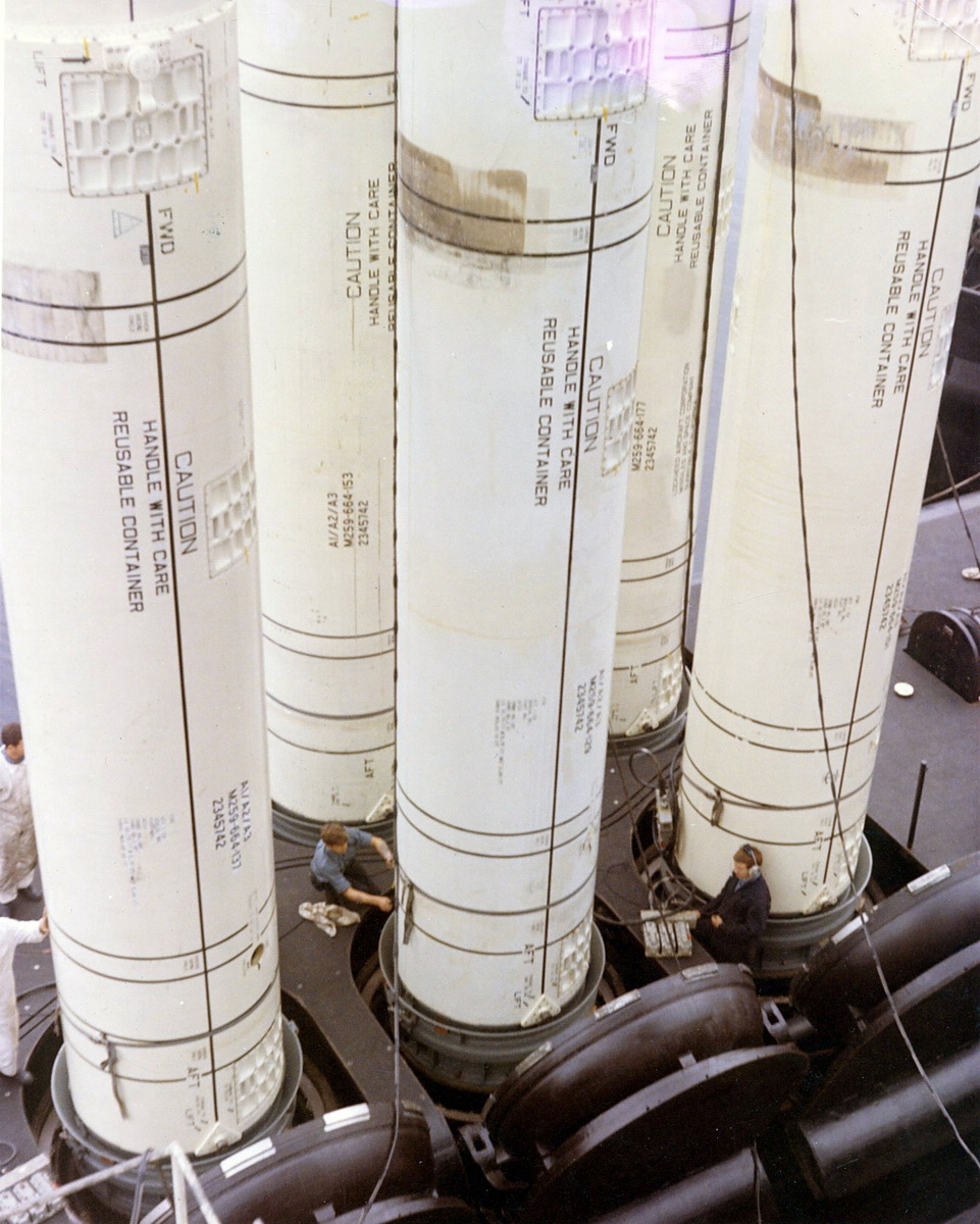
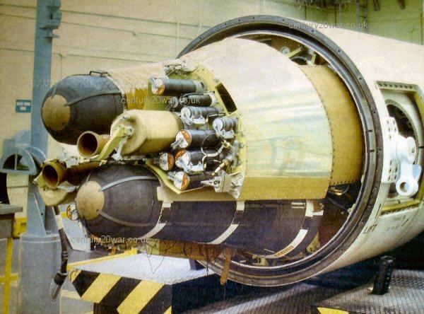
The missile compartment and the Resolution-class SSBNs' missile firing control system were fully borrowed from the U.S. Lafayette-class SSBNs. The missile compartment contains 16 Mk7 launchers. Each of them consists of a shaft, a hydraulically driven lid, a seal lid, a steel launch cup, a membrane and equipment for feeding low-temperature steam-gas mixture produced by an individual gas generator for each PU. To access the rocket systems, five hatches are equipped on the launch unit body.
Mk122 missile launch subsystem provides launch of missiles. The missile is ejected from the launch cup by using the pressure of a low-temperature steam-gas mixture. The system ensures the discharge of SLBMs from a depth of no more than 40 m to a height of about 10 m above the water surface. All 16 missiles could be launched in 16 minutes. Launch only underwater.
Characteristics:
| The length of the rocket, m | 9,86 |
| The diameter of the rocket, m | 1.37 |
| The weight of a packed SLBM, t. | 16,6 |
| Mass of combat equipment (stage of dilution, SLC ABM, 2 BB), t | 0,988 |
| Flight range, km | 3610 |
| Circular probable deviation, m. | 450 |
| Number of BB, pcs. | 2 |
| BB power, kt. | 225 |
| 1-stage engine traction at sea level, kN | 356 |
| Apogee height of PPP trajectory, km | 1000 |
Sources:
- The real meaning of the words: a pedantic glossary of British nuclear weapons by www.mcis.soton.ac.uk & R. Moore. UK, 2004.
- Strategic Defence Review / by Secretary of State for Defence G. Robertson presented to Parliament. London, UK, 1998.
- The Future of Britain’s WMD / by D.Plesch. The Foreign Policy Centre, London, UK, 2006.
- Ядерная политика и ядерное вооружение Великобритании / М. Сосновский, «Национальная оборона», №2, 2006.
- А.А. Шумилин «Авиационно-космические системы США». Москва, «Вече», 2005.
- www.lockheedmartin.com
- www.baesystems.com
- www.skomer.u-net.com
- www.astronautix.com
- www.nuclearweaponarchive.org
- www.globalsecurity.org
- www.fas.org
- www.arms.ru
- www.militaryparitet.com
- sci.military.naval
- www.dodmedia.osd.mil
- en.wikipedia.org (B. Burnell pictures, 2006)