Since the second half of the 70s, the transformation of the U.S. political leadership's views on the prospects of nuclear war begins. Taking into account the opinion of the majority of scientists that even a retaliatory Soviet nuclear strike would be fatal for the US, it decided to accept the theory of limited nuclear war for one TVD, namely, the European one. New nuclear weapons were needed for its implementation. The administration of President J. Carter allocated funds for the development and production of a highly effective strategic sea-based system "Trident".
This project was to be implemented in two phases. The first phase was to rearm 12 J. Madison Type SSBNs with Trident C4 missiles and to build and commission 8 new-generation Ohio Type SSBNs with 24 similar missiles. In the second phase, it was planned to build another 14 SSBNs and equip all the boats of this project with the new Trident D5 SLBMs with higher tactical and technical characteristics.
The general contractor is Lockheed Missiles and Space Company. It was adopted for service with the U.S. Navy in 1979.
Composition:
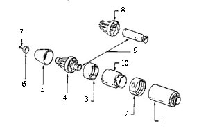
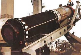
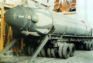
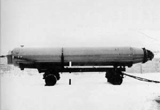
The UGM-96A "Trident-1" rocket is designed in a three-step circuit. The third stage is located in the central opening of the instrument compartment and the head part. Rocket solid fuel engines (RSTT) of all three stages of the "Trident-1" are made of materials with improved characteristics (aramid fiber, Kevlar-49, as a binder epoxy is used) and have a swinging nozzle of lightweight design. Kevlar-49 has higher specific strength and modulus of elasticity compared to glass fiber. The choice of aramid fibre gave a gain in weight as well as an increase in range. The engines are equipped with high-energy solid fuel - nitrolane, with a density of 1.84 g/cm3 and a specific impulse of 271 kg/s/kg. As a plasticizer, polyurethane rubber is used.
The Trident-1 rocket has one oscillating nozzle on each stage to provide pitch and yaw control. The nozzle is made of composite materials (on the basis of graphite) with lower weight and greater resistance to erosion. Control of the traction vector (TPV) on the active section of the trajectory along the pitch and yaw is carried out due to the nozzle deflection, and roll control is not carried out on the section of the marching engines operation. The roll deflection accumulated during RDTT operation is compensated for during the operation of the head engine unit. The heel angles of UHT nozzles are small and do not exceed 6-7°. The maximum rotation angle of the nozzle is determined based on the value of possible accidental deviations caused by an underwater launch and the missile's turn. Nozzle rotation angle during stage separation (for trajectory correction) is usually 2-3°, and during the rest of the flight - 0.5°. The first and second stages of the missile have the same UHV system design, while the third stage is much smaller. They include three main elements: a gunpowder pressure accumulator that provides gas (temperature 1200°C) to the hydraulic block; a turbine that drives a centrifugal pump; and a hydraulic power drive with pipelines. The working speed of the turbine and the rigidly connected centrifugal pump is 100-130 thousand rpm. The UHT system of the "Trident-1" rocket, unlike the "Poseidon-SZ", does not have a gear reducer that connects the turbine to the pump and reduces the pump speed (up to 6000 rpm). This has led to a reduction in their weight and increased reliability. In addition, in the UHT system, the steel hydraulic lines used in the Poseidon-SZ rocket were replaced with Teflon lines. The hydraulic fluid in the centrifugal pump has an operating temperature of 200-260°C. RDTs of all stages of "Trident-1" SLBM operate until fuel is completely burned out.
The use of lighter materials in the RDTT hulls, nozzles and elements of HHV devices, as well as the use of rocket fuel with a higher specific impulse, the modernization of the thrust vector control device and the introduction of the third stage have increased the range of the Trident-1 missile by about 2300 km compared to the Poseidon-SZ.
The guidance system for the Trident-1 SLBM controls the missile's flight both during the operation of its marching engines and during the warhead deployment phase. The main elements of the guidance system are a gyrostabilized platform on which the gyro devices and the astro-sensor are placed, as well as an on-board computer that generates control signals. To ensure normal operation of the guidance system, it uses a temperature control subsystem, which includes temperature sensors and inertial device heaters, as well as water cooling. In the Trident-1 SLBM, the instrument compartment is located on the third stage of the missile. It accommodates the equipment and devices of inertial guidance system with astro-correction. Inertial navigation devices of the missiles have an accumulated error in the range of 1480 m per flight hour. To reduce this error in the Trident-1 SLBM along with the improvement of mechanical units of inertial devices, in particular, the use of air bearings for gyroscopes (it allowed to avoid errors caused by heating, wear and tear, the thermal impact of the rotating bearing contact with the surface), astro-correction was introduced. This is done by clarifying the position of the missile in space when one or two stars close to the target area are observed. To correct the range, measurements of the elevation angle of the star relative to the local vertical at launch are used, and horizontal component measurements are used to correct the azimuth. For astronautical measurements, Trident-1 missiles are equipped with an optical telescope and a star sensor on the viscera, which form a single unit with a complex of inertial devices.
Application of new achievements in the field of microelectronics on the Trident-1 SLBM allowed reducing the weight of the electronic equipment block in the guidance and control system by 50% compared to a similar block on the Poseidon-SZ rocket. In particular, the electronic equipment integration rate on the Polaris-AZ missiles was 0.25 conventional elements in 1 cm3, on the Poseidon-SZ - 1, on the Trident-1 - 30 (due to the use of thin-film hybrid schemes).
The civil defense of Trident-1 missiles consists of a combat compartment, a warhead deployment system (stage), a guidance subsystem and a head envelope with a nose aerodynamic needle. The combat compartment carries eight W-76 warheads arranged in a circle. Each has a power rating of approximately 100 kt. The warhead dilution system compensates for errors in deflection of the HF to the target and provides a corrective maneuver in targeting the warheads. It includes a propulsion system consisting of two solid propellant gas generators and a subsystem of small nozzles with control valves that control the speed of the head end, as well as its orientation and stabilization, during warhead dilution. The role of the gas generator is performed by a powder pressure accumulator (operating temperature 1650°C, specific impulse 236 kg/s/kg, high pressure 33 kg/s/cm2, low pressure 12 kg/s/cm2). Previously, the operating temperature of the gas was 450°C lower in the Poseidon-SSLBM warhead deployment system and the specific impulse was 15% lower.
The gas is fed through an inlet pipeline to four control nozzle blocks feeding a total of 16 nozzles (four front, four rear and eight roll stabilizers). The weight of the warhead piston system is 295 kg, the weight of fuel is 193 kg, the maximum operating time after separation of the third stage is 7 min.
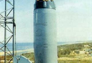
The head fairing of the Trident-1 SLBM is made of special spruce veneer, and its nose part is made of phenolic fiberglass. It is noted in the foreign press that the use of special spruce veneer provided much better characteristics of the head part when leaving the atmosphere than other tested materials. At the same time with the exit from the dense layers of the atmosphere only the outer layer of the fairing is charred, and the other layers provide good protection of the instrument compartment and HF elements. The discharge (and removal from the missile's flight path) of the fairing is performed at the second stage engine operating area by means of solid propellant engines.
The nose aerodynamic needle is used on Trident missiles to reduce aerodynamic drag and increase the firing range with the existing shape of their head fairings. On the Trident-1 SLBM, the aerodynamic needle is recessed in the cowling and its six parts are telescopically extended under the influence of a powder pressure accumulator for 100 ms at a height of 600 m. The needle reduces the maximum force of frontal aerodynamic resistance in the active part of the trajectory from 18 thousand to 9 thousand kgf. The application of such a scheme has resulted in an increase in the range of 550 km for the Trident-1 SLBM and 325 km for the Poseidon-SSL as compared to the Polaris-AZ missile, which has a similar shape of a head fairing.
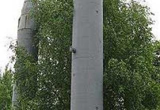
The SLBM launchers are the most important component of the launch complex and are designed for storing, servicing and launching the missile. The main elements of each booster are: a mine, a launch cup, a hydropneumatic system, a diaphragm, valves, a plug connector, a steam supply subsystem, a control and inspection subsystem of all components of the launcher.
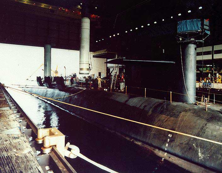
The mine is a cylindrical steel structure. It is fixed fixed in the SSBN case. From above, the shaft is closed by a hydraulically operated lid (equally strong with a robust SSBN casing), under which there is a membrane preventing ingress of inlet water into the shaft when the lid is opened. A steel starting cup is installed inside the shaft. The ring gap between the walls of the shaft and the glass is filled with elastomeric polymer. In the gap between the inner surface of the glass and the missile are placed shock-absorbing and obturizing belts. In the beaker, the BPL is mounted on a support ring, which ensures its azimuthal display. In the lower part of the rocket there are four shock-absorbing devices and four centering cylinders. In the gap between the walls of the shaft and the starting cup there are some devices (shock absorbers) designed to damp the shock loads on the rocket.
The "Trident-1" launch cup is mounted to a robust SSBN case with 20-30 boots supported by hydraulic shock absorbers, with a membrane on top. The rigid shell of the 6.3 mm thick membrane has a dome-shaped shape (2.02 m diameter and 0.71 m height). It is made of phenolic resin reinforced with asbestos. To the inner surface of the membrane is glued low density polyurethane foam with open cells and honeycomb material made in the shape of the missile nose. This ensures that the SLBM is protected from power and heat loads when the membrane is opened by profiled explosive charges mounted on the inner surface of the shell. Opening the shell breaks down into several parts: the central and side parts.
To access the missile systems and components for inspection and maintenance, each mine has necks and hatches located at different levels. The Trident-1 SLBM launch shaft is equipped with a new type of plug connector to connect the missile's instruments to the on-board firing control system. It is automatically disconnected when the missile is launched.
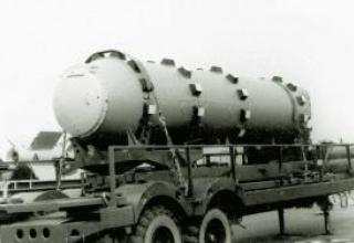
A powder pressure accumulator is used for firing Trident-1 missiles from the mine. The gases it generates pass through a water chamber and are partially cooled. The resulting low-temperature steam enters the lower part of the launch cup and pushes out the missile. The transition to combined cycle gas, according to U.S. experts, allowed the rocket to increase its firing weight without increasing the volume of the ejection system. The Trident-1 SLBM launch shaft has been equipped with a system of overpressure generation before missile launch, a cooling chamber and a shaft closure device of this type. The size of the launch cup on Ohio SSBNs is 15% larger in diameter and 30% larger in height than on Lafayette boats. This was done taking into account the possibility of further placement of Trident-2 SLBMs on the first eight "Ohio" type ships.
The Missile Firing Control System is designed to calculate the firing data and input them into the missile, perform prelaunch checks and monitor the readiness of the equipment for launch. The Lafayette type SSBN is equipped with the Mk88 mod missile firing control system. 2, for "Ohio" a new system of Mk98 mod. is developed. О. Unlike similar systems of the Polaris missile system, they allow the redirection of missiles located in the mines of patrol SSBNs to newly assigned targets.
The missile firing control system includes missile launch control posts, navigation and control posts for the subsystem of missile ejection from the mine. It is based on a computer. The missile firing control post is located in the central SSBN post. The necessary data describing the condition of all missiles and the preparation of auxiliary subsystems for firing are displayed on its special panel. The Lafayette type SSBN consists of 16 rows of green control lights, showing the preparation stages and degree of readiness for flight. In the center of the lower part of the console there is a hole for the starting key. The navigation post provides data describing the location of the carrier and its movement elements, as well as the magnet and gravity fields of the Earth in the area where the SSBNs are located. These, as well as information from the control and missile release subsystem, are entered into a shipboard computer.
Functioning of the missile system.
With the receipt of a signal order to launch missiles, the commander of the boat declares the alert. After verifying the authenticity of the order, the commander gives the command to bring the submarine into technical readiness ISy, which is the highest degree of readiness. This command clarifies the coordinates of the ship, the speed is reduced to values that provide the launch of missiles, the boat floats to a depth of about 30 meters. As soon as the navigation post as well as the control and missile release subsystem post from the mines are ready, the SSBN commander inserts the launch key into the corresponding hole of the firing control panel and switches it. By this action, he gives the command to the missile compartment of the boat for direct prelaunch preparation of the missile system. Before the missile is launched, the pressure in the launch shaft is aligned with the override, and then the strong cover of the shaft is opened. The intake water is then blocked only by a relatively thin membrane below.
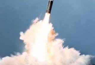
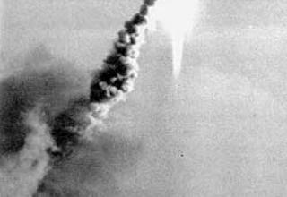
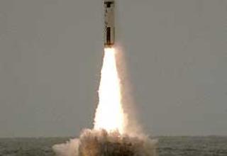
The missile is launched directly by the commander of the weapon unit (rocket and torpedo) using a red trigger (black for training launches), which is connected to the computer using a special cable. The powder pressure accumulator is then activated. The gases it generates pass through the chamber with water and are partially cooled. The resulting low-temperature steam enters the lower part of the launch cup and pushes the missile out of the mine. As the missile moves upwards, it breaks the membrane and the intake water flows freely into the shaft. After the rocket leaves the shaft cover automatically closes and the intake water in the shaft is discharged into a special substitution tank inside the strong boat body. When the SSBN moves in the launch cup, it is exposed to a significant reactive force and after leaving the shaft, the intake intake water is pressurized. The helmsman, with the help of special automatic devices controlling the operation of gyroscopic stabilizers and water ballast pumping, keeps the boat from falling to the depth.
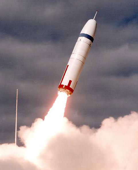
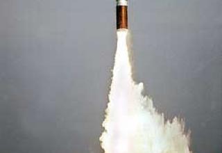
After uncontrolled movement in the water column, the rocket comes to the surface. The first stage engine of the SLBM is switched on at an altitude of 10-30 m above sea level by a signal from an acceleration sensor. Together with the missile, pieces of the launch cup seal are ejected to the water surface.
The rocket then rises vertically and, when it reaches a certain speed, starts to practice the flight program. Upon completion of the first stage engine at an altitude of approximately 20 km, it is separated and the second stage engine is switched on, and the first stage's hull is fired off. The third stage engine of the Trident-1 is switched on in a similar manner. When the missile is moving in the active section of the trajectory, its flight is controlled by deflecting the nozzles of the stage engines. After separation of the third stage, the warhead deployment phase begins. The head unit with the instrument compartment continues its ballistic trajectory flight. Correction of the flight path by the engine of the head unit, targeting and firing of warheads are carried out.
The WMIRV type head unit uses the so-called "bus principle": the CS, after correcting its location, aims at the first target and fires the warhead that follows the ballistic trajectory towards the target, then the CS ("bus"), after correcting its location by the warhead propulsion system, aims at the second target and fires the next warhead. The same procedure is repeated for each warhead. If a single target needs to be hit, a program is laid out in the MS that allows for a time-varying strike (in the MS of the MRV type, after the second stage engine has been targeted, all warheads are fired simultaneously).
In 15-40 minutes after the missile is launched, the warheads reach their targets. The flight time depends on the removal of the area of the SSBN firing position from the missile's target and trajectory.
Characteristics:
| Maximum firing range, km | 7 400 |
| Shooting accuracy (CWO), m | 300 |
| Number of steps, pcs. | 3 |
| Stairwell arrangement | Tandem |
| Guidance System | Inertial with astrocorrection |
| Start mass, t | 32 |
| Diameter, m | 1,88 |
| Length, m | 10,36 |
| The length of the first step, m | 4,16 |
| Second step length, m | 3,37 |
| Length of the third step, m | 2,83 |
| Method of dividing the steps | Hot |
| Head geometry | Born to life with spherical blunting + aerodynamic needle |
| Head blunting radius, m. | 0,266 |
| How to separate the head part | Interrogation |
| Weight of payload, kg | 1280 |
| The weight of the first stage is full, t | 32 |
| Weight of the second stage is full, t | 11,85 |
| The mass of the third stage is full, t | 3,2 |
| Charge weight with first stage reservation, kg | 18820 |
| Charge weight with second stage reservation, kg | 7260 |
| Mass of charge with third stage reservation, kg | 1810 |
| First stage nozzle drowning factor | 0,5 |
| Second stage nozzle drowning factor | 0,3 |
| Third stage nozzle drowning factor | 0,3 |
| Starting tractor-traction of the first stage | 2,313 |
| Second stage starting tractor system | 3,06 |
| Starting thrust of the third stage | 3,38 |
| Rated draught second stage RDTT, tc | 54,4 |
| Mass of fuel RDTT second stage, t | 7,26 |
| Nominal thrust of third stage RDTT, tc. | 18,1 |
| Weight of third stage RDTT fuel, t | 1,81 |
| Fuel brand | Nitrolan |
| Fuel density, kg/m3 | 1770 |
| Earth's specific impulse | 2880 |
Testing:

The complex proved itself well in combat operations, in particular, a significant number of TOS-2 and TOS-2A missiles were used during the combat operations in the Persian Gulf area in 1991. According to the estimates of the foreign press, one of the Marine Corps units destroyed 93 armored targets, while using 120 vehicles.
The modernization of this complex is currently in progress. The works are aimed at further increasing the combat efficiency of the MANPAD, reducing its mass and dimensional characteristics and the amount of equipment included in its composition.
For example, a new ITAS launcher was developed on the instructions of the Ground Forces Command. Its main difference from the basic model is that all devices are combined into a compact unit, it uses a new combined sight, laser rangefinder and improved missile control equipment. Technical capabilities of the sight allow to engage targets in any visibility conditions at the maximum range of missile launch. In addition, it has advanced lifting and rotating mechanisms, as well as diagnostic and training equipment.
Raytheon has started to develop a missile capable of hitting targets on a "shot for forget" basis. It plans to develop a propulsion system using gel fuel, a more powerful BC, and a new thermal imaging homing head. At the same time, the missile should remain compatible with all TOW systems, including ITAS, and its launch range is expected to be at least 5 km.
Modernization of TOS complexes is carried out in other countries as well. In Denmark, for example, ETS (Elevated Tow System) has been successfully tested to verify that ETS can be launched from behind a shelter. This system is capable of engaging armoured fixed and moving targets at a range of up to 4 km with TOP missiles of all modifications. ETS is a tracked armored vehicle M113A1 with a stabilized platform rising to a height of 7 m, which combines into a single compact unit optronic system and PU for four missiles in the armored body. The platform is elevated to the required height for reconnaissance purposes and for launching PTUR by means of a hydraulic drive from a camping position.
The optical-electronic system includes a combined sight with optical and thermal channels with a tracking system, a laser rangefinder and a unit of the missile's flight control equipment. In addition, the advanced lifting and turning mechanisms of the PU ensure that the platform turns in two-speed mode. All incoming information is displayed on the displays of the commander and gunner-operator of the complex, located at workstations inside the APC. This complex is capable of carrying 20 missiles, four of which are in the AP platform. Recharge of missiles can be carried out in automatic and manual modes.
According to the developers, the installation of the platform with a lifting mechanism is also possible for other types of combat vehicles, in particular, the LAV series.
Sources:
- В.Красненский, В.Грабов "РАКЕТНЫЕ КОМПЛЕКСЫ ПЛАРБ СТРАН НАТО", "Зарубежное военное обозрение"
- http://www.fas.org/nuke/guide/usa/slbm/c-4.htm
- http://www.warships1.com/Weapons/WMUS_Trident-C4.htm