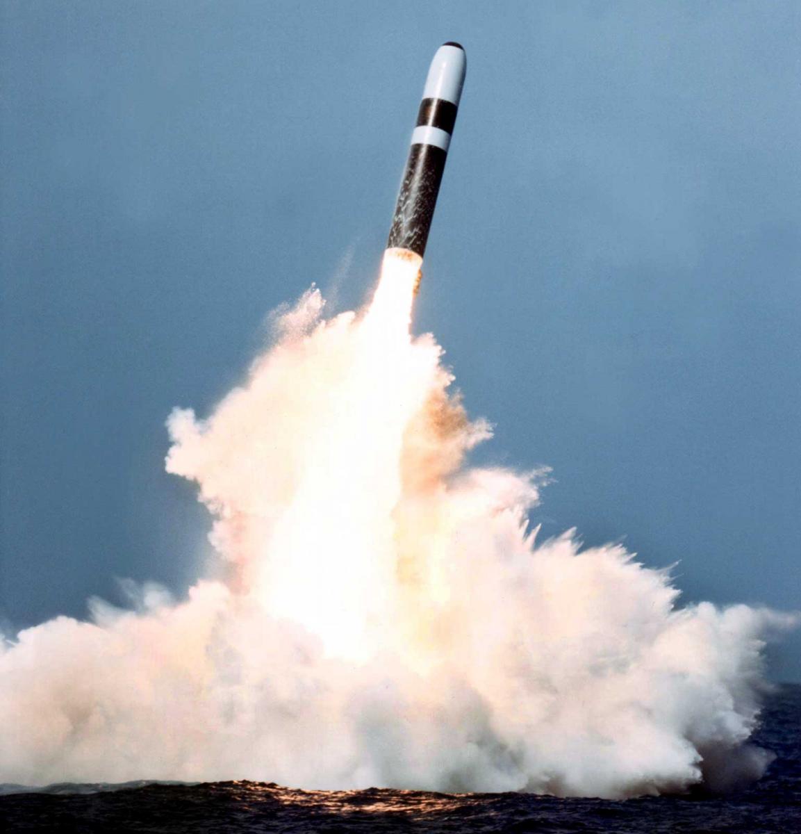
In 1990, testing of the new Trident-2 submarine ballistic missile (SLBM) was completed and it was adopted for service. This SLBM, like its predecessor Trident-1, is part of the Trident strategic missile system, which is carried by the Ohio and Lafayette type nuclear-powered submarines (SSBNs). The system complex of this missile carrier provides combat missions anywhere in the world ocean, including the high Arctic latitudes, and the accuracy of firing combined with powerful warheads allows the missiles to effectively engage small protected targets, such as ICBM silos, command centers and other military facilities. According to U.S. experts, the modernization capabilities laid down in the development of the Trident-2 missile system allow the missile to remain in service with maritime SNF for a considerable period of time.
The Trident-2 system is considerably superior to the Trident-1 in terms of the power of nuclear charges and their quantity, accuracy and range. The increased power of nuclear warheads and increased accuracy of firing provide the Trident-2 SLBM with the ability to effectively engage heavily protected small targets, including ICBM silo launchers.
The main companies involved in the development of the Trident-2 SLBM:
- Lockheed Missiles and Space (Sunnyvale, California) is the lead developer;
- Hercules u Morton Thiokol (Magna, Utah) - RDTT of 1st and 2nd stages;
- Chemical Sistems (San Jose, California, United Technologies) - RDTT Level 3;
- Ford Aerospace (Newport Beach, California) - Engine valve block;
- Atlantic Research (Gainesville, Virginia) - Step 3 gas generators;
- General Electric (Philadelphia, Pennsylvania) - head end;
- Draper Laboratory, Cambridge, Massachusetts, a guidance system.
The flight and design testing programme was completed in February 1990 and included 20 ground-based launches and five from SSBNs:
- Mar 21 1989 Four seconds after the start of the flight, at an altitude of 68 m (225 ft), there was a rocket explosion. The failure was due to a mechanical or electronic malfunction in the cardan suspension of the nozzle controlling the rocket. The cause of the rocket's self-destruction was high angular velocity and overload.
- 02.08.89 The test was successful.
- 15.08.89 The RDTT of Stage 1 ignited normally, but the automatic missile detonation system was triggered for 8 seconds after the launch and 4 seconds after the launch from under water. The cause of the missile's explosion was a damage to the thrust vector control system of the RTT and, as a result, a deviation from the calculated flight path. The damage was also caused by power cables of the first stage, which initiated the onboard self-liquidation system.
- 04.12.89 The test was successful.
- 13.12.89 The test was successful.
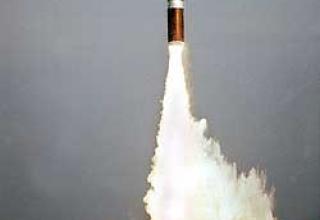
- 13.12.89 The test was successful. The rocket was launched from a depth of 37.5 m. The submarine was moving at a speed of 3-4 knots relative to water. Absolute speed was equal to zero. The course of the PL was 175 degrees, the launch azimuth was 97 degrees.
- 15.12.90 Fourth successful launch in a row from underwater position.
- 16.01.90 The test was successful.
Test launches from a submarine revealed the need for modifications to the first stage of the missile and the launch shaft, which eventually led to a delay in taking the missile into service and reducing its range. The designers had to solve the problem of the nozzle block protection from the water column impact that occurs when the SLBM leaves the water. After completion of tests Trident D5 entered service in 1990. The Trident-2 is part of the Trident strategic missile system, which is carried by Ohio and Lafayette type nuclear missile submarines (SSBNs).
The U.S. Naval Command expects that the Trident-2 missile system, created using the latest technologies and materials, will remain in service in the next 20-30 years, with its constant improvement. In particular, for the Trident missiles the development of maneuvering warheads with which there are high hopes to improve the efficiency of overcoming the enemy's anti-missile defense system and the defeat of deeply buried point objects. In particular, the Trident-2 SLBM is planned to be equipped with maneuvering MARV (Maneouverable Re-entry Vehicle) warheads with radar sensors or inertial guidance systems on a laser gyroscope. Guidance accuracy (MARV), according to calculations of American specialists, can be 45 and 90 m respectively. For this warhead, a penetrating type nuclear weapon is being developed. According to experts from the Livermore Radiation Laboratory (California), technological difficulties in the design of such a warhead have already been overcome and tests of prototypes have been conducted. After separation from the HC, the warhead maneuvers to evade the enemy's anti-missile defenses. Upon approaching the ground surface, its trajectory changes and its speed decreases, which ensures penetration into the ground at the appropriate entrance angle. When penetrating to the ground surface to a depth of several meters, it explodes. This type of weapon is designed to destroy various objects, including highly protected underground command centers of military and political leadership, command centers of strategic forces, nuclear missiles and other objects.
Composition:
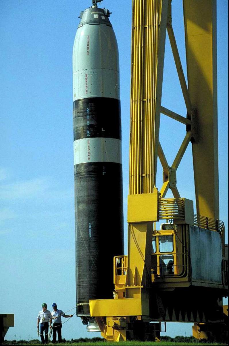
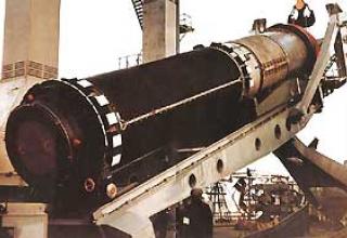
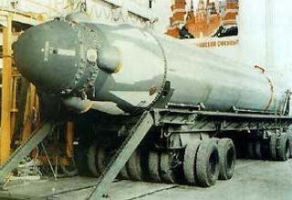
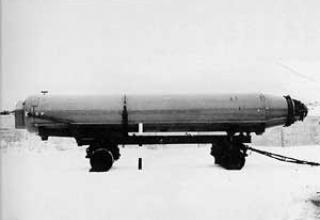
The UGM-96A Trident-2 rocket (see the diagram) is designed in a three-step circuit. In this case the third stage is located in the central opening of the instrument compartment and the head part. Rocket solid fuel engines (RSTT) of all three stages of the Trident-2 are made of materials with improved characteristics (aramid fiber, Kevlar-49, as a binder epoxy is used) and have a swinging nozzle of lightweight design. Kevlar-49 has higher specific strength and modulus of elasticity compared to glass fiber. The choice of aramid fibre gave a gain in weight as well as an increase in range. The engines are equipped with high-energy solid fuel - nitrolane, with a density of 1.85 g/cm3 and a specific impulse of 281 kg/s/kg. As a plasticizer, polyurethane rubber is used. The Trident-2 rocket has one oscillating nozzle on each stage to provide pitch and yaw control.
Nozzle is made of composite materials (based on graphite), which have a lower mass and greater resistance to erosion. Control of the traction vector (Traction Vector) on the active section of the trajectory on the pitch and yaw is carried out due to the nozzle deflection, and the heel control on the section of the marching engines is not carried out. The roll deflection accumulated during RDTT operation is compensated for during the operation of the head engine unit. The roll angles of UHT nozzles are small and do not exceed 6-7°. The maximum rotation angle of the nozzle is determined based on the value of possible accidental deviations caused by an underwater launch and the missile's turn. Nozzle rotation angle during stage separation (for trajectory correction) is usually 2-3°, and during the rest of the flight - 0.5°. The first and second stages of the missile have the same UHV system design, while the third stage is much smaller. They include three main elements: a gunpowder pressure accumulator that provides gas (temperature 1200°C) to the hydraulic block; a turbine that drives a centrifugal pump; and a hydraulic power drive with pipelines. The operating speed of the turbine and the rigidly connected centrifugal pump is 100-130 thousand rpm. The UHT system of the Trident-2 missile, unlike the Poseidon-SZ, does not have a gear reducer connecting the turbine to the pump and reducing the pump speed (up to 6000 rpm). This has led to a reduction in their weight and increased reliability. In addition, in the UHT system, the steel hydraulic piping used on the Poseidon-SZ rocket has been replaced with Teflon piping. The hydraulic fluid in the centrifugal pump has an operating temperature of 200-260°C. RDTs of all stages of the Trident-2 SLBM operate until the fuel is completely burned out. Application of new achievements in the field of microelectronics on the Trident-2 SLBM allowed to reduce the weight of the electronic equipment block in the guidance and control system by 50% in comparison with a similar block on the Poseidon-SZ rocket. In particular, the electronic equipment integration rate on Polaris-AZ missiles was 0.25 conventional elements in 1 cm3, on Poseidon-SZ - 1, on Trident-2 - 30 (due to the use of thin-film hybrid schemes).
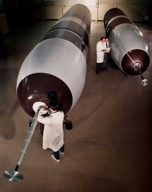
The head end (HF) includes an instrument compartment, combat compartment, propulsion system and head fairing with a nose aerodynamic needle. The Trident-2 combat compartment accommodates up to eight W-88 warheads of 475 kt each, or up to 14 W-76 warheads of 100 kt each, arranged on a circumference. Their mass is 2.2 to 2.5 tonnes. The HC propulsion system consists of solid-fuel gas generators and control nozzles, with the help of which the head end speed, its orientation and stabilization are regulated. On the Trident-1, it includes two gas generators (gunpowder pressure accumulator - operating temperature 1650 ° C, specific impulse 236 s, high pressure 33 kgf/cm2, low pressure 12 kge/cm2) and 16 nozzles (four front, four rear and eight stabilizers on the roll). Fuel weight of the engine unit is 193 kg, the maximum operating time after separation of the third stage is 7 minutes. The Trident-2 HC propulsion system uses four solid propellant gas generators developed by Atlantic Research.
The last stage of modernization of the missile is to equip the BB W76-1/Mk4 new fuses MS4700 ("Penetrating Aggression"). The new fuse makes it possible to compensate for the missed target during the flight due to an earlier blast over the target. The magnitude of the miss is estimated at an altitude of 60-80 kilometers after analyzing the real position of the warhead and its flight path relative to the designated place of detonation. It is estimated that the probability of hitting a mine launcher with 10,000 pounds per square inch protection increases from 0.5 to 0.86.
The head fairing is designed to protect the missile's head part while it is moving in water and dense layers of the atmosphere. The head cowl is reset at the operating site of the second stage engine. The nose aerodynamic needle is used on Trident-2 missiles to reduce aerodynamic drag and increase the range under existing forms of their head fairings. It is recessed in the cowling and is telescopically extended by a powder pressure accumulator. On the Trident-1 rocket the needle has six components, extends at a height of 600m for 100 ms and reduces aerodynamic resistance by 50 percent. The aerodynamic needle on the Trident-2 SLBM has seven retractable parts.
The instrument compartment accommodates various systems (control and guidance, data entry for warhead detonation, warhead deployment), power supplies and other equipment. The control and guidance system controls the missile's flight during its marching and warhead deployment phases. It develops commands to switch all three stages of the missile on, off, separate all three stages of the RDT, switch on the HC propulsion system, perform manoeuvres to correct the flight path of the SLBMs and aim the warheads. The control and guidance system of the Trident-2 Mk5 type SLBM includes two electronic units installed in the lower (rear) part of the instrument compartment. The first unit (0.42X0.43X0.23 m in size, weighing 30 kg) houses a computer that generates control signals and control circuits. The second unit (0.355 m in diameter and 38.5 kg in weight) houses a gyrostabilized platform with two gyroscopes, three accelerometers, an astro-sensor and temperature control equipment. The warhead deployment system provides for the development of commands to manoeuvre the GC when targeting the warheads and their separation. It is installed at the top (front) of the instrument compartment. The warhead blast data entry system records the necessary information during prelaunch preparation and generates data on the blast height of each warhead.
Onboard and ground computing systems
The missile firing control system is designed to calculate the firing data and input them into the missile, perform a prelaunch check of the missile system readiness for operation, control the missile launch process and subsequent operations.
It solves the following tasks:
- calculating the firing data and entering it into the missile;
- Provision of data for the SLBM storage and launch system for pre- and post-launch operations;
- Connecting the SLBM to the ship's power supply sources before direct launch;
- Verification of all missile systems and shipboard systems involved in pre-launch, launch and post-launch operations;
- verifying that the time sequence for preparing and launching the missiles is observed;
- automatic detection and search for malfunctions in the complex;
- providing the possibility of combat calculation training on missile firing (simulator mode);
- providing permanent registration of data characterizing the missile complex condition.
Rocket Firing Control System Mk98 mod. It includes two main computers, a network of peripheral computers, a rocket shooting control panel, data transmission lines and auxiliary equipment. The main elements of the SLS are located at the Missile Shooting Control Station, and the control panel at the SSBN Central Station. The AN/UYK-7 main computers ensure the coordination of the firing control system in various variants of operation and its centralized computer service. Each computer is placed in three racks and includes up to 12 units (size 1X0.8 m). Each of them contains several hundred standard SEM military electronic modules. The computer has two CPUs, two adapters and two I/O controllers, a storage device and a set of interfaces. Either processor of each computer has access to all data stored in the machine. This increases the reliability of the solution to the problems of missile flight programming and control of the missile system. The computer has a total memory capacity of 245 kbytes (32-bit words) and the speed of 660 thousand op./s.
The network of peripheral computers provides additional data processing, storage, display and input to the main computers. It includes small-size (up to 100 kg) AN/UYK-20 computers (16-bit machine with the speed of 1330 oper./s and 64 kbytes of RAM), two recording subsystems, a display, two disk drives and a tape recorder. The rocket shooting control panel is designed to control all stages of preparation and degrees of readiness of the missile system to launch missiles, the command to launch and control post-start operations. It is equipped with a control panel, controls and locking systems of the missile system, means of intra-ship communication. The Trident-2 missile system has certain technical differences from the previous Mk98 system. O (in particular, it uses more modern computers AN/UYK-43), but solves similar tasks and has the same logic of functioning. It provides sequential launch of SLBMs both in automatic and manual modes by series or single missiles.
The Trident's general-purpose rocket system provides the Trident with 450 V and 60 Hz power, 120 V and 400 Hz AC power, 120 V and 60 Hz AC power, as well as hydraulic power with 250 kg/cm2 pressure and compressed air.
The maintenance of the specified depth, roll and differential of the SSBNs during missile launches is ensured by means of the shipborne stabilization system of the launch platform and maintenance of the specified launch depth, which includes systems of drainage and substitution of the missile mass, as well as special automatic machines. It is controlled from the control panel of the ship-to-ship systems.
The ship-wide climate and environmental control system provides the necessary air temperature, relative humidity, pressure, radiation control, air composition and other characteristics both in the BCPP and in all the service and living areas of the boat. The control of microclimate parameters is carried out with the help of the board installed in each compartment.
The SSBN navigation system ensures constant delivery of accurate data on the location, depth and speed of the submarine to the missile system. It includes an autonomous inertial system, optical and visual observation facilities, reception and computing equipment of satellite navigation systems, receivers of radio navigation systems and other equipment. Ohio" type SSBN navigation system with Trident-1 missiles includes two inertial systems SINS Mk2 mod.7, high-precision internal correction unit ESGM, RNS LORAN-C AN/BRN-5 receiving and retrieval equipment SNS NAVSTAR and RNS Omega MX-1105, navigation sonar AN/BQN-31, a generator of reference frequencies, computer, remote control and auxiliary equipment. The complex provides performance of the specified accuracy characteristics of Trident-1 SLBM (KVO 300-450 m) within 100 hours without correction by external navigation systems. Ohio" type SSBN navigation system with Trident-2 missiles provides higher accuracy characteristics of missile firing (120 m KVO) and supports them during extended time between corrections on external navigation sources. This was achieved by improving existing systems and introducing new ones. Thus, more advanced computers, digital interfaces, navigation sonar and other innovations were installed. A navigation inertial system ESGN, equipment for determining the location and speed of SSBNs on underwater hydroacoustic beacons-responders, magnetometer system were introduced.
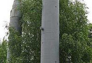
The storage and launch system (see diagram) is designed for storage and maintenance, overload and impact protection, and for the accidental release and launch of SSBN missiles in an underwater or surface position. On Ohio type submarines, this system is called Mk35 mod. O (on ships with the Trident-1 complex) and the Mk35 mod. 1 (for Trident-2 complex), and Mk24 on converted Lafayette type SSBNs. The Mk35 mod.O. systems include 24 mine launchers, SLBM ejection subsystem, missile launch monitoring and control subsystem, and loading equipment. The PU consists of a shaft, a hydraulically driven lid, sealing and locking the lid, a starting cup, a diaphragm, two plug connectors, steam and gas mixture feeding equipment, four control hatches, 11 electric, pneumatic and optical sensors.
The launchers are the most important component of the complex and are designed for storing, servicing and launching the missile. The main elements of each PU are: a mine, a launch cup, a hydropneumatic system, a diaphragm, valves, a plug connector, a steam supply subsystem, a control and inspection subsystem of all components of the launcher. The shaft is a cylindrical steel structure and is an integral part of the SSBN case. From above, it is closed by a hydraulically operated cap, which provides waterproofing and withstands the same pressure as a sturdy boat hull. There is a seal between the lid and the shaft neck. To prevent unauthorized opening, the lid is equipped with a locking device, which also provides blocking of the O-ring of the PU lid with mechanisms for opening the control and adjustment hatches. This prevents the simultaneous opening of the PU lid and the test hatches, except during the loading and unloading phase of the missile.
Inside the mine there is a steel starter cup. The o-ring gap between the walls of the shaft and the beaker has an elastomeric polymer seal that acts as shock absorbers. In the gap between the inner surface of the cup and the missile there are shock-absorbing and obturizing belts. In the starting cup, the BPL is mounted on a support ring, which ensures its azimuthal display. The ring is mounted on shock-absorbing devices and centering cylinders. From above, the starting cup is covered by a membrane that prevents ingress of intake water into the shaft when the lid is opened. The hard shell of the 6.3 mm thick membrane has a dome-shaped shape with a diameter of 2.02 m and a height of 0.7 m. It is made of phenolic resin reinforced with asbestos. To the inner surface of the membrane is glued low-density polyurethane foam with open cells and honeycomb material, made in the shape of the nose of the rocket. This provides protection of the missile from power and heat loads when the membrane is opened by means of profiled explosive charges mounted on the inner surface of the shell. Opening the shell breaks down into several parts.
The launch cup of the Trident-2 missile system, manufactured by Westinghouse Electric, is made of the same grade of steel as the Trident-1 SLBM. However, due to the large size of the missile, its diameter is 15% and its height 30% larger. Urethane is also used as sealing material between the walls of the shaft and the glass, along with neoprene. The composition of the urethane composite material and the sealing configuration have been selected based on the higher impact and vibration loads encountered during the launch of the Trident-2 SLBM.
The PU is equipped with two plug connectors of a new type (umbilical cord), which are automatically unbuckled at the moment of missile launch. The connectors are used to feed the instrument compartment of the rocket power supply and enter the necessary firing data. The PU steam-gas mixture feed equipment is part of the SLBM ejection subsystem. A steam-gas mixture feed pipe and a submarine chamber are installed directly into the PU. This equipment is located practically at the base of the mine. The PU has four control and adjustment hatches, which provide access to the equipment and components of the rocket and launch equipment for their inspection and maintenance. One hatch is located at the level of the first deck of the SSBN missile compartment, two hatch are located at the level of the second deck (providing access to the SLBM instrument compartment and jack), one hatch is located below the level of the fourth deck (access to the missile chamber). The hatch opening mechanism is locked with the PU cover opening mechanism.
Each PU has a BRIL emergency water cooling subsystem and is equipped with 11 sensors that monitor temperature, air humidity, moisture quantity and pressure. In order to control the required temperature (approximately 29°C) the PU is equipped with temperature sensors, which in case of inadmissible temperature deviation send signals to the thermal control system. Relative air humidity (30% and less) is controlled by three sensors located in the missile chamber, in the lower part and near the instrument compartment of the starting glass. As the humidity increases, the sensors give a signal to the control panel installed in the missile compartment and to the missile firing control station. On command from the post, the relative humidity is reduced by running dry air under pressure through the PU. The presence of moisture in the PU is detected by probes installed in the missile chamber and the steam-gas mixture feed pipe. When the stylus comes into contact with water, a corresponding alarm is triggered. Water is fetched in the same way as wet air.
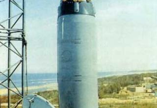
The missile ejection subsystem consists of 24 independent units. Each unit includes a gas generator (gunpowder pressure accumulator), an ignition device, a cooling chamber, a steam-gas mixture feed pipe, a missile chamber, a protective coating as well as control equipment. The gases generated by the powder pressure accumulator pass through the chamber with water (cooling chamber), are mixed with it in certain proportions and form low-temperature steam. This steam-gas mixture flows through a socket into the missile chamber with uniform acceleration and, when a certain pressure is reached, pushes the missile out of the launch cup with a force sufficient to eject the body weighing 32 t from a given depth (30-40 m) to a height of more than 10 m above the water surface. The Trident-2 SLBM ejection subsystem creates almost twice the pressure of the vapor-gas mixture, which allows even a missile weighing 57.5 tons to be ejected from the same depth to the same height. The launch monitoring and control subsystem is designed to control the prelaunch preparation of the booster, to signal the activation of the SLBM ejection subsystem, to control the launch process and postlaunch operations. It includes the launch control panel, launch safety equipment and test equipment. The start control panel is used to display signals allowing to control actuation and functioning of the starting system, as well as to generate necessary signals to change the operating mode of subsystems and equipment of the SRSL storage and start system. It is located at the rocket firing control post. The launch safety equipment controls and generates signals for the SLBM ejection subsystem and the rocket launch control system (SLS). It provides a permissive signal for the SLS for prelaunch, launch and postlaunch operations of five SLBM launchers simultaneously. The equipment includes a unit with 24 launch safety modules, a switching panel for the SLBM ejection subsystem in the test mode and switches for the operating modes of the SLBM storage and launch system.
The control and test equipment includes three blocks, each of which monitors the condition and functioning of eight PCs, as well as five blocks that monitor the solution of logical, signal and test functions of the electronic equipment of the storage and start-up system of the SLF. All blocks are installed in the SSBN missile compartment.
Upon receiving a signal order to launch missiles, the commander of the boat declares the alert. After verifying the authenticity of the order, the commander gives the command to bring the submarine into technical readiness ISy, which is the highest level of readiness. This command clarifies the coordinates of the ship, the speed is reduced to values that provide the launch of missiles, the boat floats to a depth of about 30 meters. As soon as the navigation post as well as the control and missile release subsystem post from the mines are ready, the SSBN commander inserts the launch key into the corresponding hole of the firing control panel and switches it. By this action, he gives the command to the missile compartment of the boat for direct prelaunch preparation of the missile system. Before the missile is launched, the pressure in the launch shaft is aligned with the override, and then the strong cover of the shaft is opened. The intake water is then blocked only by a relatively thin membrane below.
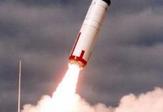
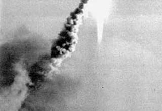
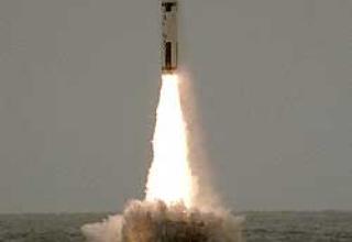
The missile is directly launched by the commander of the combat unit of the weapon (rocket and torpedo) using a trigger mechanism with a red handle (black for training launches), which is connected to the computer using a special cable. The powder pressure accumulator is then activated. The gases it generates pass through the water chamber and are partially cooled. The resulting low-temperature steam enters the lower part of the launch cup and pushes the missile out of the mine. The Polaris-AZ rocket system used high-pressure air, which was supplied to the skull of the missile through a system of valves on a strictly defined schedule, precisely maintained by a special automatic equipment. This provided a given mode of motion of the rocket in the launch cup and its acceleration with acceleration up to 10g at a rate of exit from the mine 45-50 m / s. When the rocket moves upwards, it breaks the membrane and the intake water freely enters the mine. After the rocket leaves the mine cover automatically closes, and the intake water located in the mine is discharged into a special substitution tank inside the strong boat hull. When the SSBN moves in the launch cup, it is exposed to a significant reactive force and after leaving the shaft, the intake intake water is pressurized. The helmsman, with the help of special automatic devices controlling the operation of gyroscopic stabilizers and water ballast pumping, keeps the boat from falling to the depth. After uncontrolled movement in the water column, the rocket comes to the surface. The first stage engine of the SLBM is switched on at an altitude of 10-30 m above sea level by a signal from an acceleration sensor. Together with the missile, pieces of the launch cup seal are ejected to the water surface.
The rocket then rises vertically and, when it reaches a certain speed, starts to practice the flight program. Upon completion of the first stage engine at an altitude of approximately 20 km, it is separated and the second stage engine is switched on, and the first stage's hull is fired off. When the missile is moving in the active section of the trajectory, its flight is controlled by deflecting the nozzles of the stage engines. After separation of the third stage, the warhead deployment phase begins. The head unit with the instrument compartment continues its ballistic trajectory flight. Correction of the flight path by the engine of the head unit, targeting and firing of warheads are carried out. The WIRV type head unit uses the so-called "bus principle": the MS, after correcting its location, targets the first target and fires the warhead that follows the ballistic trajectory towards the target, then the MS ("bus"), after correcting its location by the warhead propulsion system, targets the second target and fires the next warhead. The same procedure is repeated for each warhead. If a single target needs to be hit, a program is laid out in the MS that allows for a time-varying strike (in the MS of the MRV type, after the second stage engine has been targeted, all warheads are fired simultaneously). In 15-40 minutes after the missile is launched, the warheads reach the targets. The flight time depends on the removal of the area of the SSBN firing position from the missile's target and trajectory.
Characteristics:
| General characteristics | |
| Maximum firing range, km | 11000 |
| Circular probable deviation, m. | 120 |
| The diameter of the rocket, m | 2,11 |
| The length of the rocket is complete, m | 13,42 |
| The mass of the projectile, t. | 57,5 |
| Charge power, kt | 100 Кт (W76) or 475 Кт (W88) |
| Number of warheads | 14 W76 or 8 W88 |
| Stage I | |
| Relative mass of fuel, m | 0,616 |
| Starting stage traction | 2,48 |
| Weight, kg: - full scale steps - remote control structures - fuel and charge reservation - remote-controlled |
37918 2414 35505 37918 |
| Dimensions, mm: - length - maximal diameter |
6720 2110 |
| Average mass flow rate, kg / s | 563,5 |
| Average pressure in the combustion chamber, kgf/m2 | 115 |
| Full time remote control, with | 63 |
| Specific traction pulse in the void, kgs | 286,8 |
| Stage II | |
| Relative mass of fuel, m | 0,258 |
| Starting stage traction | 3,22 |
| Weight, kg: - full scale steps - remote control structures - fuel and charge reservation - remote-controlled |
16103 1248 14885 16103 |
| Dimensions, mm: - length - maximal diameter |
3200 2110 |
| Average mass flow rate, kg / s | 323 |
| Average pressure in the combustion chamber, kgf/m2 | 97 |
| Full time remote control, with | 64 |
| Specific traction pulse in the void, kgs | 299,1 |
| III stage | |
| Relative mass of fuel, m | 0,054 |
| Starting stage traction | 5,98 |
| Weight, kg: - full scale steps - remote control structures - fuel and charge reservation - remote-controlled |
3432 281 3153 3432 |
| Dimensions, mm: - length - maximal diameter |
3480 1110 |
| Average mass flow rate, kg / s | 70 |
| Average pressure in the combustion chamber, kgf/m2 | 73 |
| Full time remote control, with | 45 |
| Specific traction pulse in the void, kgs | 306,3 |
| Speed (approx. 30 m above sea level), mph. | 15000 |
Testing:

The complex proved itself well in combat operations, in particular, a significant number of TOS-2 and TOS-2A missiles were used during the combat operations in the Persian Gulf area in 1991. According to the estimates of the foreign press, one of the Marine Corps units destroyed 93 armored targets, while using 120 vehicles.
The modernization of this complex is currently in progress. The works are aimed at further increasing the combat efficiency of the MANPAD, reducing its mass and dimensional characteristics and the amount of equipment included in its composition.
For example, a new ITAS launcher was developed on the instructions of the Ground Forces Command. Its main difference from the basic model is that all devices are combined into a compact unit, it uses a new combined sight, laser rangefinder and improved missile control equipment. Technical capabilities of the sight allow to engage targets in any visibility conditions at the maximum range of missile launch. In addition, it has advanced lifting and rotating mechanisms, as well as diagnostic and training equipment.
Raytheon has started to develop a missile capable of hitting targets on a "shot for forget" basis. It plans to develop a propulsion system using gel fuel, a more powerful BC, and a new thermal imaging homing head. At the same time, the missile should remain compatible with all TOW systems, including ITAS, and its launch range is expected to be at least 5 km.
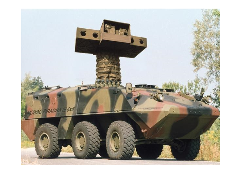
Modernization of TOS complexes is carried out in other countries as well. In Denmark, for example, ETS (Elevated Tow System) has been successfully tested to verify that ETS can be launched from behind a shelter. This system is capable of engaging armoured fixed and moving targets at a range of up to 4 km with TOP missiles of all modifications. ETS is a tracked armored vehicle M113A1 with a stabilized platform rising to a height of 7 m, which combines into a single compact unit optronic system and PU for four missiles in the armored body. The platform is elevated to the required height for reconnaissance purposes and for launching PTUR by means of a hydraulic drive from a camping position.
The optical-electronic system includes a combined sight with optical and thermal channels with a tracking system, a laser rangefinder and a unit of the missile's flight control equipment. In addition, the advanced lifting and turning mechanisms of the PU ensure that the platform turns in two-speed mode. All incoming information is displayed on the displays of the commander and gunner-operator of the complex, located at workstations inside the APC. This complex is capable of carrying 20 missiles, four of which are in the AP platform. Recharge of missiles can be carried out in automatic and manual modes.
According to the developers, the installation of the platform with a lifting mechanism is also possible for other types of combat vehicles, in particular, the LAV series.
Sources:
- Журнал "Зарубежное военное обозрение"
- В.Красненский, В.Грабов. «Ракетные комплексы ПЛАРБ странНАТО».
- www.warships1.com/Weapons/WMUS_Trident-C4.htm
- http://www.fas.org/nuke/guide/usa/slbm/c-4.htm