In early 1956, U.S. President D. Eisenhower approved plans for a maritime strategic nuclear missile system. It was envisaged that the entire program would be implemented in several stages with the increase in combat capabilities of both missiles and their carriers.
Initially, it was planned to create a missile for submarines on the basis of Jupiter MRBM, work on which was in full swing at the time, but without apparent success. This could undermine the timely implementation of plans for the first stage. In addition, fleet specialists considered the presence of missiles with explosive liquid fuel components on the boat to be an excessive risk. Therefore, the leadership of the Navy applied to the US Department of Defense for permission to develop a missile for the fleet. Given the difficulties with the development of liquid propellant missiles in general and for submarine missiles in particular, they immediately relied on solid propellant rocket engines (SPRT), the technology for the production of which by 1957 had already been tested. At the same time, work was underway on a nuclear submarine project - a carrier of nuclear missile weapons.
In 1956, contracts were concluded with the company "Lockheed Martin" for the development of a conceptual design of the missile and the creation of engines for it - with the company "Aerojet-General". By the end of that year, the tactical and technical requirements for the system were developed and the optimal dimensions of the submarine, its missile compartment and the missile were determined.
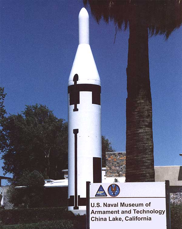
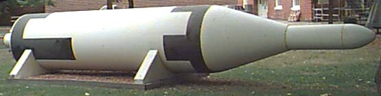
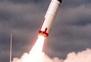
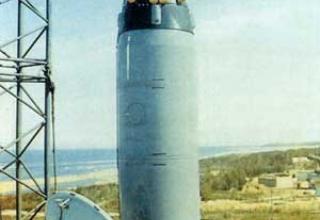
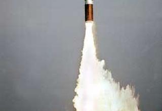
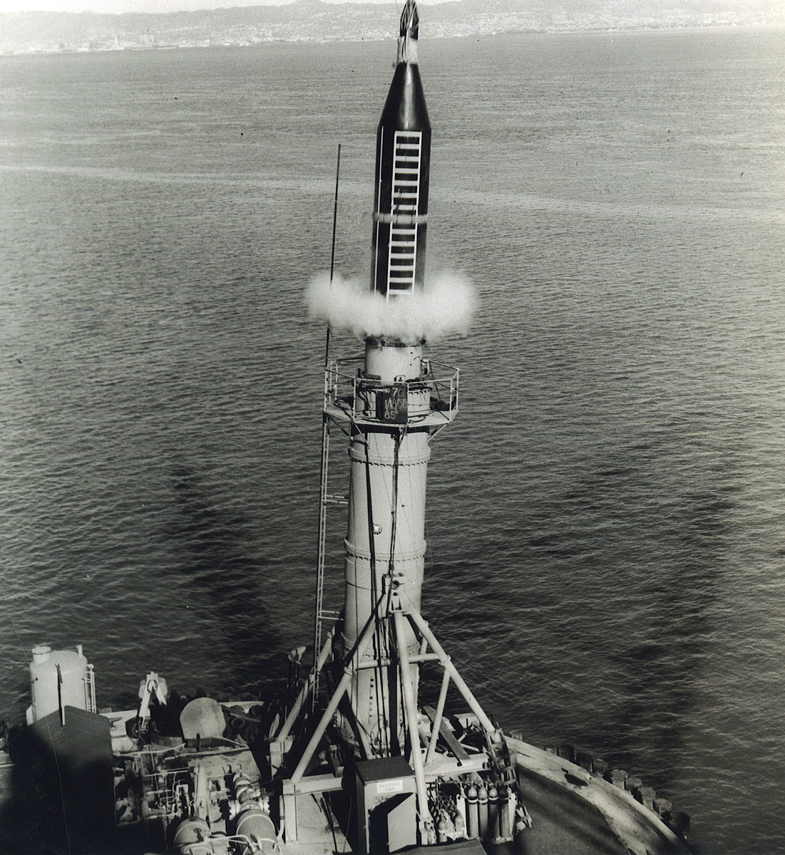
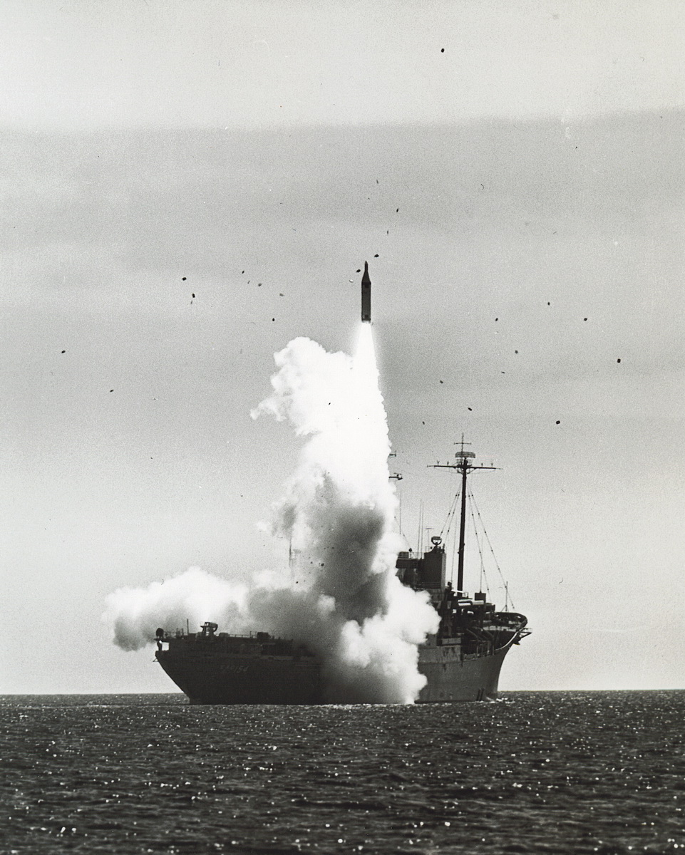
In June 1957, it was decided to start the development of a "mortar" launch from the surface position of the mass-dimensioned models of missiles from a prototype control gear, developed by the company Westinghouse. The prototype was called "Peashooter" (see photo), and shot tests were conducted at a naval shipyard in San Francisco. After successful completion of these tests, it was decided to begin testing a submarine launch that was conducted at the Pop-Up prototype (see photo), located at a naval weapons test site near San Clemente Island, California. The first cast test was performed in March 1958. In September 1958, the flight test of the UGM-27A "Polaris A-1" missile (see photo) began at the Eastern Test Site. The first launches ended unsuccessfully. On April 20, 1959, the next (fifth) launch was successful. The whole year was spent on development of rocket systems and the head end. Since the standard missile carrier was not yet ready, it was decided to launch the missiles from a specially equipped ship Observation Island, in 1959-1960, 6 launches were made (see photo).
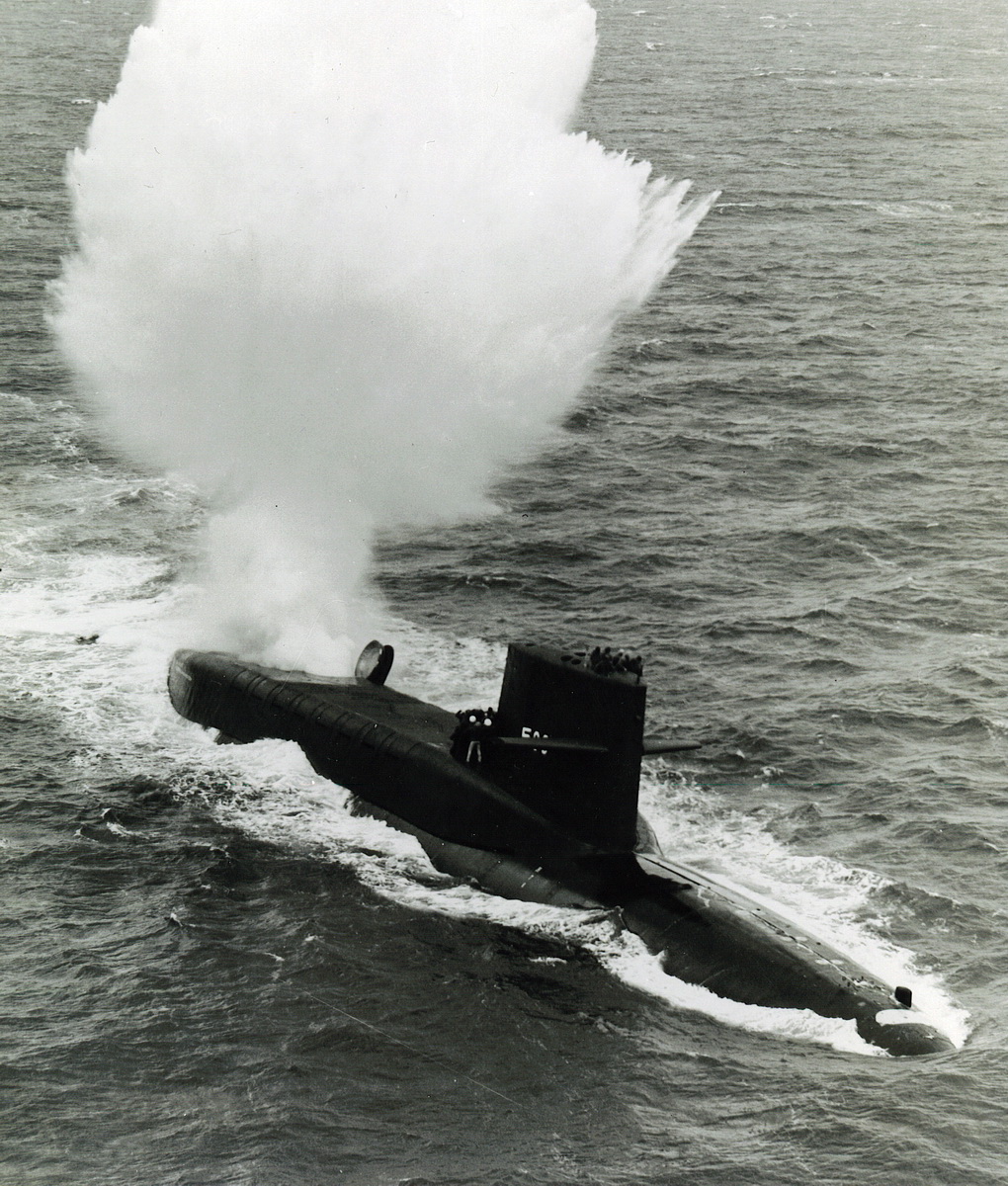
The program of launches from the nuclear submarine "George Washington", handed over to the fleet the same year, was completed.
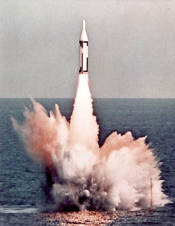
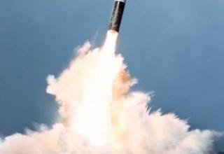
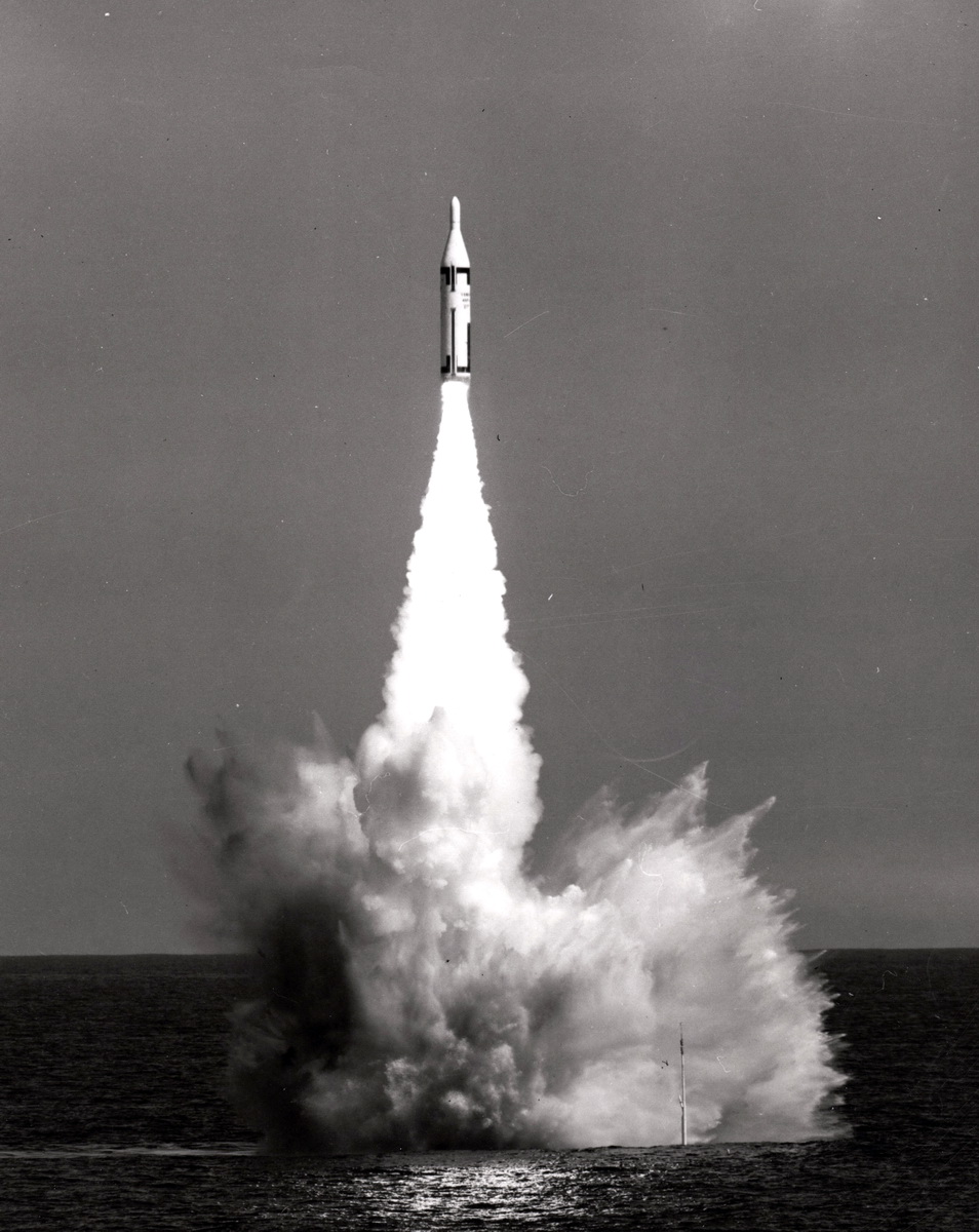
On July 20, 1960, this SSBN was the first in the world to successfully launch a ballistic missile from a submarine near Cape Canaveral, Florida, at that time (see photo). Less than two hours later, a second missile was successfully launched (see photo). The message (see photo) was immediately relayed directly from the boat to U.S. President D. Eisenhower and was succinctly "George Washington launches the Polaris from depth to target. No comment" . In total, it was carried out: from September 1958 to October 1959, 17 test launches of the pilot rocket AX (5 successful, 11 partially successful), and from September 1959 to November 1960. 40 test launches of the A1X pre-production missile (28 successful, 11 partially successful). The pre-production missiles differed from the experimental missiles by an increased fuel reserve at the second stage and a higher energy fuel. In October 1960, the missile system "Polaris A-1" was adopted for service.
Five JWDC type SSBNs were carriers of these missiles. The UGM-27A "Polaris A-1" SLBMs were in service for only five years until the mid 1960s. Disengagement of missiles began in June 1964 and ended in October 1965.
No doubt, it is worth mentioning the various test programs in which the missile Polaris A-1. The first of them was the development of the principle of thrust vector control by injecting gas into the critical part of the nozzle - this method was planned to apply on the newest SLBM Polaris A-3, which was created at that time. For this purpose, in September and December 1961, 2 launches of the A1X rocket with a non-standard experimental second stage were performed. In the first case, a mixture of freon and nitrogen was used for injection. According to the results of the launch it was decided to abandon the nitrogen, and the amount of remaining Freon was reduced by 2/3. Both launches were successful, so the road for the new traction vector control principle was opened. The mentioned launches were not included in the above mentioned general classification of A1X rocket launches.
The second was the ISEP (Interservice Signature Experiments Program), the main goal of which was to study all aspects related to the detection of missile warheads by means of SPRN and ABM of a possible enemy. Polaris A-1 missiles were launched from Observation Island towards Kwajalein Atoll. A total of 6 launches were made between 1967 and 1968. The missiles launched differed from the regular missiles by the presence of a special transition compartment, which allowed to use the combat unit Mk2 from the Polaris A-3 missile. All launches were successful.
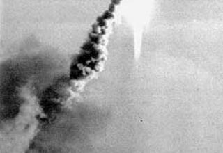
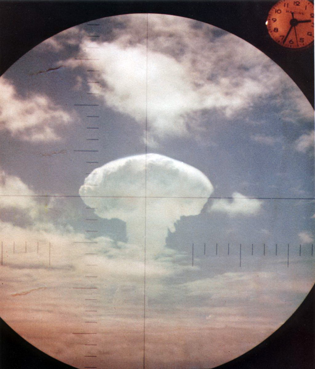
A special feature of the Polaris A-1 rocket career is its successful participation in May 1962 in a unique experiment - Operation Frigate Bird, which was part of a large-scale series of American trials "Dominic". In the course of this operation, the nuclear missile carrier Ethan Allen launched the Polaris A1 SLBM from the underwater position in standard equipment with a 600ct thermonuclear BC W-47. The launch was conducted from the Pacific Ocean area around Christmas Island and ended in an explosion of ammunition at an altitude of about 3 km at the design point (see photo).
Composition:
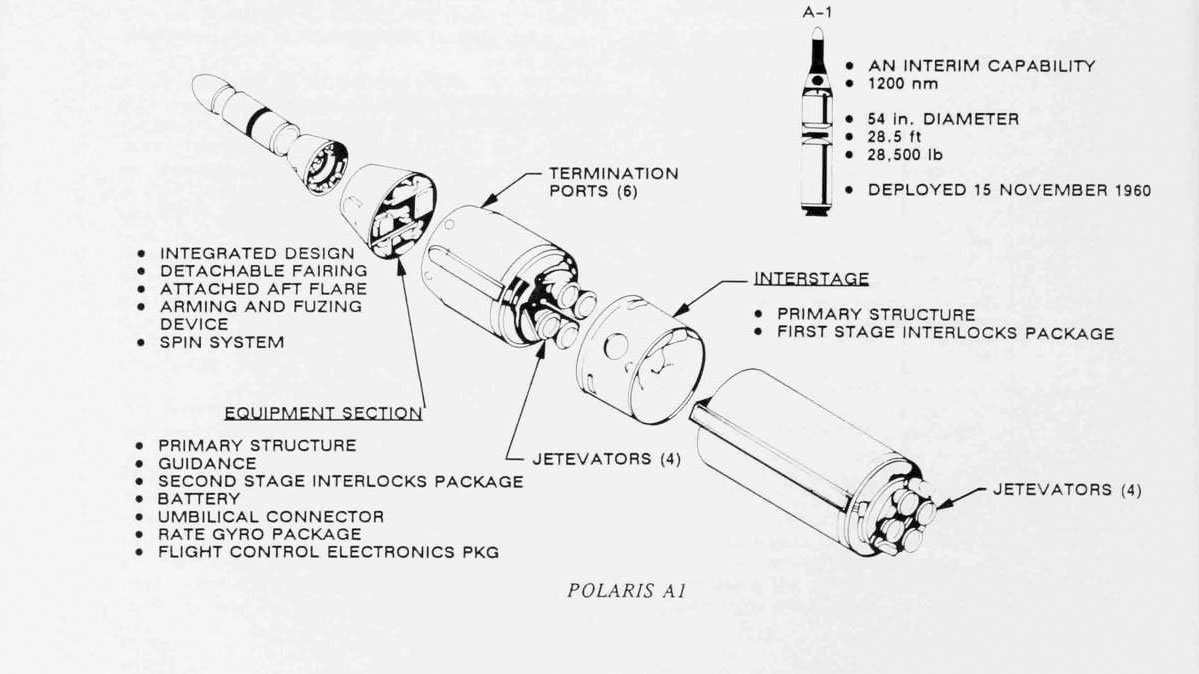
The UGM-27A SLBM is a two-stage, step-by-step rocket (see diagram). The welded case of the missile is made of high-strength vanadium stainless steel AMZ-256 with yield strength 160-170 kg/mm2.
RDTT has been used as engines for both rocket stages. The first stage engine with a thrust of 45 tons runs on polyurethane with aluminum and ammonium perchlorate additive (fuel ANP 2639). Aluminum additive is used to increase fuel combustion stability and specific impulse increase up to 245-250 kg*sec/kg (theoretical impulse 266 kg*sec/kg). The temperature in the first stage engine chamber reaches 2700° C. The second stage engine has a thrust of 9 tons (according to other data - 4 tons) and runs on polyurethane in a mixture with a copolymer of polybutadiene and acrylic acid (fuel ANP 2673 on missiles AX, and ANP 2655 on missiles A1X and serial A1P), has a thrust cut-off device that allows you to reach different ranges. The charge in the RDTT of each stage has an inner cavity in the form of a six-beam star, passing along the longitudinal axis of the fuel charge.
Each engine is equipped with four nozzles. To control the engine thrust vector on both stages of the rocket, ring deflectors mounted on each of the nozzles and articulated with appropriate hydraulic drives are used. Tests have shown the high efficiency of this type of steering device and, in particular, the ability to put the rocket on a trajectory even if the vertical deflection of the rocket at the time of switching on the first stage engine by 40°. The engines are powered by an electromechanical device and a powerful fuse, while the tail plugs of the nozzles, which protect the engines from water during the underwater passage of the rocket, are ejected by the pressure of the working gases released at the time of engine activation. Special experiments have shown that the serial engine of the Polaris missile normally operates after 1.5 years of storage in a special container with a microclimate of the submarine's standard launch shaft.
The missile is equipped with a 600 kt W-47 detachable in flight monoblock head unit.

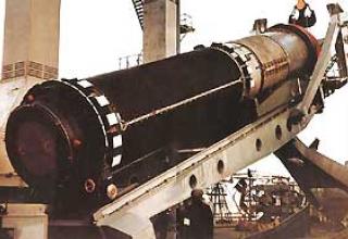
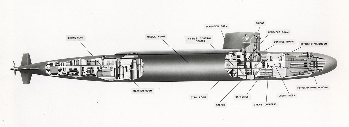
For storing and launching missiles, the missile carrier submarine has 16 launching shafts (see description) located in the middle part of the ship's hull. The mine covers, which protrude beyond the strong hull, are covered by a light streamlined superstructure, which is 40 m long on the George Washington type submarines (see diagram).
Prior to missile launch, the pressure in the launch shaft is equalized with the overhang, after which the strong cover of the shaft is opened and access to the overhang water is blocked only by a relatively thin plastic aperture located under the strong cover of the shaft. Compressed air is then delivered under the skimmer through a valve system on a strictly defined schedule, precisely maintained by a special automatic equipment, which provides a given mode of movement of the rocket in the mine. When the rocket moves upwards, it breaks the aperture and the intake water flows freely into the shaft. A special automatic substitution system blows the water ballast to compensate for the excess weight that occurs when the mine is filled with water. After the rocket is launched, the sturdy shaft lid automatically closes and the intake water located in the shaft is discharged into a special tank inside the boat.
The starting acceleration of the missile is approx. 10 g with an exit velocity of 45 m/sec and a negative acceleration of the submarine itself approx. 0.02 g. It has been determined that this acceleration of the missile does not have any significant impact on the missile's onboard equipment, sensitive mechanisms and devices.
After uncontrolled movement in the water column, the missile enters the surface at a speed of about 50 m/s. The first stage engine is automatically activated when the missile is at 10 m from the water surface. At an altitude of about 20,000 m it is separated from the rocket and at the same time the second stage engine is automatically activated. Separation of the second stage from the warhead of the missile and stop the engines are on command from the inertial guidance system of the missile at a given design point of the trajectory. The interval between missile launches to 1 minute.
The missile flight is carried out according to a predetermined program trajectory without any further adjustments from the submarine missile carrier, which places high demands on the navigation and guidance systems of the complex. The autonomous inertial control system Mk I used in the complex provides the output of the missile on a given trajectory, stabilization of its flight and shutdown of the second stage of the missile engine when reaching a given initial speed. Its onboard equipment is located in the instrument compartment, which is located in the middle part of the missile body. It accommodates a stabilized platform with accelerometers, flight control software, a block of auxiliary electrical equipment, consisting mainly of servo amplifiers and servomotors, digital counting and solving machine, power supplies and other devices. The weight of onboard guidance equipment is about 90 kg.
To ensure control over the technical condition of the missiles and objective assessment of the possibility of their combat use on the submarine is a special automatic system OAT1SO, the switchboard which serves all blocks of each of 16 missiles and can perform the following operations:
- a continuous inspection of all major missile blocks from the moment it is loaded onto the ship;
- periodic experimental testing of the missile's launch and control systems,
- a full inspection of the missile's nodes during prelaunch preparation.
The OAT1SO system consists of a program block with a reading device, a scanning system, a program switching unit, a selector, a clock generator, a comparison unit and an indicator block with a printing unit.
Prior to missile launch, the onboard equipment is connected to the Mk-80 ship's Missile Firing Control System (SARS), which was first used on eleven George Washington and Ethan Allen submarines. At the same time, data specifying the trajectory coordinates and the speed of the missile's flight at the end of the boost phase begin to flow continuously to the control equipment. At the same time, gyroscopes are oriented and promoted, etc.
The PURS equipment consists of a computer with memory blocks storing information about possible targets, and an optoelectric device used to control the orientation of a stabilized platform.
By means of PURS computing machine the following main tasks are solved:
- the missile's trajectory is calculated;
- the local vertical is determined and the orientation of the stabilized platform of the missile's onboard equipment is performed; the values of the required missile flight speed at the end of the active section of the trajectory are entered into the onboard control system;
- deviations in the accelerometer's scaling factors are recorded;
- continuous monitoring of onboard equipment of the PURS and readiness of the missile for launch is performed.
The onboard PURS system is connected with the SINS navigation complex, from which data on the current coordinates of the ship itself and other parameters characterizing its movement, as well as data on the positions of the true meridian and the ship itself relative to the vertical during the rocking.
The following assemblies and devices are placed at the navigation post of the submarine missile:
- three sets of SINS system mounted on a stabilized platform;
- a stabilized periscope for use in underwater astronomy;
- radio-navigation system;
- two special computing machines of Navdak type.
Optical system of automatic tracking of stars has its own analogue-digital computer "Stardak", which is used to generate data that provide system stabilization. "Stardak receives and processes the raw data characterizing the movement of the submarine, and as a result, the periscope of the astronautical system is permanently pointed at a star chosen as a reference point. In addition, the Stardak machines calculate the coordinates of the ship itself, which are then transferred to another computer of the Navdak type.
All three sets of SINS navigation system work independently and in parallel. Their simultaneous use minimizes errors in determining the true location of the ship, because the data coming from their outputs are mutually correlated. Data from the radio-navigation system and periscopes are also fed into the computer's input, and target data are entered into the computer's memory blocks of the rocket flight control system in advance. In this way, the data produced by all control system elements are continuously compared and analysed. In case of occurrence of inadmissible value of deviation of this or that parameter in comparison with the one set in work the "Navdak" computing machine is switched on, calculating the correction and entering the corrected value of this parameter into the corresponding control system device. The navigation system of the complex also includes rocking stabilizers of the submarine with a gyroscope weighing about 23 tons.

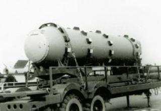
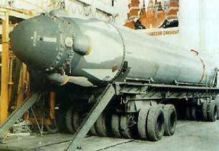
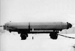
Taking into account the importance, extreme complexity and cost of the Polaris A-1 complex, great attention was paid to the development of means of transportation of the complex. For the transportation of missiles by aircraft created special shock-resistant airtight containers.
The means of transporting missiles by rail on open platforms and on highways with the help of special vehicles, and for the transportation of missiles on waterways designed a barge of catamaran type with a special hangar, capable of carrying missiles weighing up to 200 tons.
The missiles and warheads are delivered to their parking places of submarine missile carriers in containers, which are then installed together with the missiles by a crane in the launching shafts of the submarine. The missiles in containers can also be loaded on special transport vessels or floating bases (e.g. Hanley type) for delivery on submarines on the high seas.
Characteristics:
| Number of steps | 2 |
| Start weight, t | 12.7 |
| The length of the rocket, m | 8.53 |
| The diameter of the rocket, m | 1.37 |
| Flight range, km | 2220 |
| Circular probable deviation, m. | 1800 |
| 1-stage engine chamber pressure, kg/cm2 | 70 |
| Engine chamber pressure 2 steps, kg/cm2 | 35 |
| Engine traction 1 step, t | 45 |
| Engine traction 2 stages, t | 9 (4) |
| Engine running time 1 step, s | 54 |
| Engine running time 2 steps, s | 70 |
| Maximum missile flight speed, M | 10 |
Sources:
- Пронин Л.И. "Ракеты для космических исследований".
- Морозов Н.И. "Баллистические ракеты стратегического назначения". - М.: Воениздат, 1974
