The development of the Tochka divisional missile system was started by the Resolution of the Council of Ministers dated March 4, 1968. The "Tochka" complex was designed to defeat small point targets in the depth of enemy defense: ground-based reconnaissance and strike systems, control points of various types of troops, parking lots of aircraft and helicopters, reserve groups of troops, ammunition, fuel and other supplies.
Kolomenskoye Mechanical Engineering Design Bureau was appointed head performer on the subject, and S.P. Unbeaten as chief designer. The missile control system was developed at the Central Research Institute of AG. The launcher was designed and serially produced by the Barrikada software in Volgograd. Mass production of missiles was carried out by Votkinskiy Machine-Building Plant. The chassis for the launcher and transport and charging machines were manufactured in Bryansk.
The first two launches of Tochka guided missiles were made in 1971 during factory flight and design tests. Series production of the rocket was started in 1973, although the complex was officially adopted in 1976. Tochka" complex had a range of 15 to 70 km and an average circular deviation of 250 m.
In April 1971, the development of the Tochka-R modification, with a passive homing system for radio emitting targets (radar, radio stations, etc.) began. The guidance system provided a range of target acquisition at a distance of at least 15 km. It was assumed that the accuracy of pointing "Tochki-R" on a continuously operating target does not exceed 45 m, and the area of engagement is more than two hectares.
In 1989, a modified 9K79-1 "Tochka-U" complex was adopted for service. The main difference is its long range and accuracy.
In the west the complex received the designation SS-21 "Scarab".
Composition:
Composition of the missile system 9K79 (9K79-1) (see the gallery of images of the complex machines) :
- Militant means
- Missiles:
- 9M79B with 10 kt nuclear warhead AA-60.
- 9M79B1 with a nuclear warhead of particular importance AA-86.
- 9M79B2 with nuclear warhead AA-92
- 9M79F with a concentrated 9H123F (9M79-1F) fragmentation and blast furnace combat unit.
- 9M79K with cluster warhead 9H123K (9M79-1K)
- 9M79FR with shrapnel-phase BC and passive radar SNS 9H123F-R (9M79-1FR)
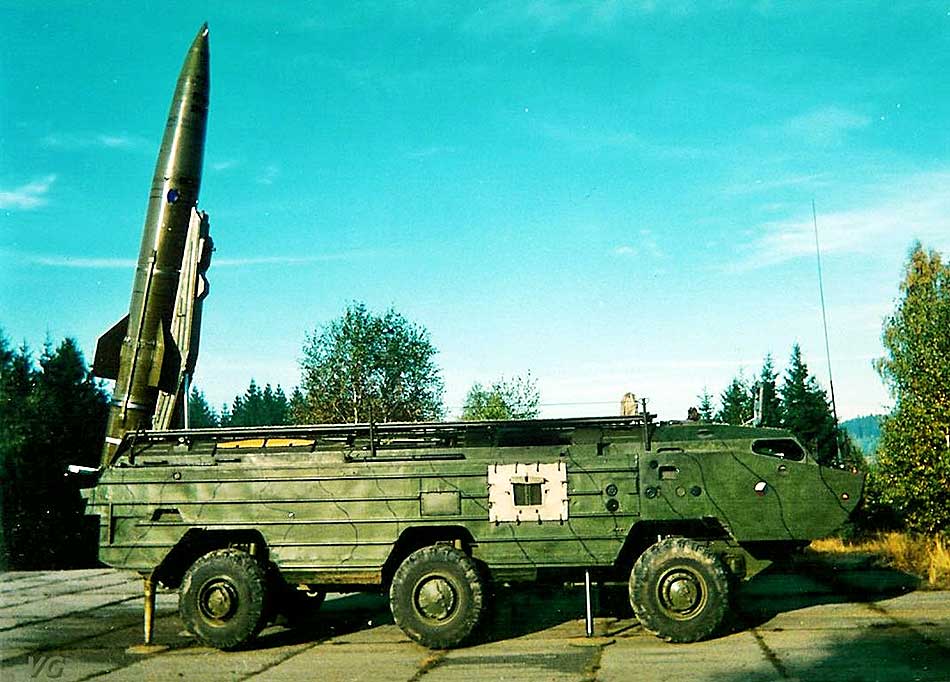
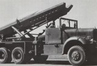
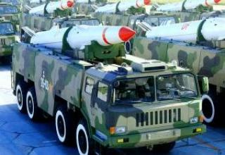
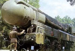
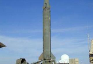
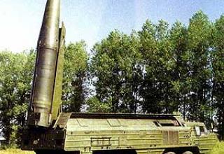
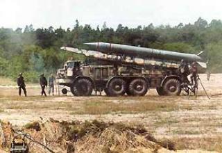
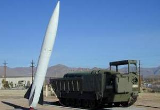
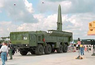
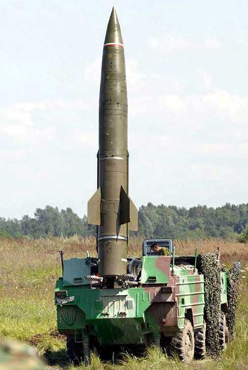
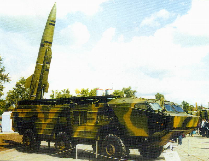
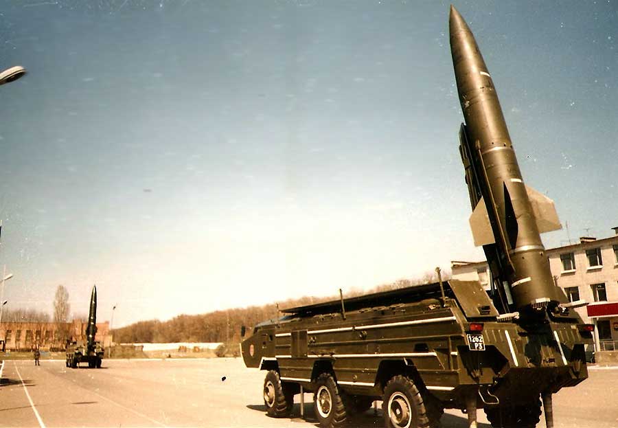
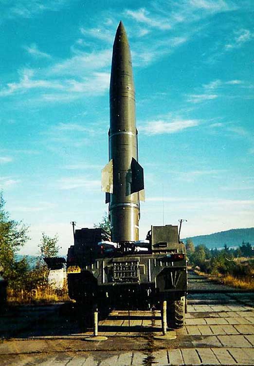
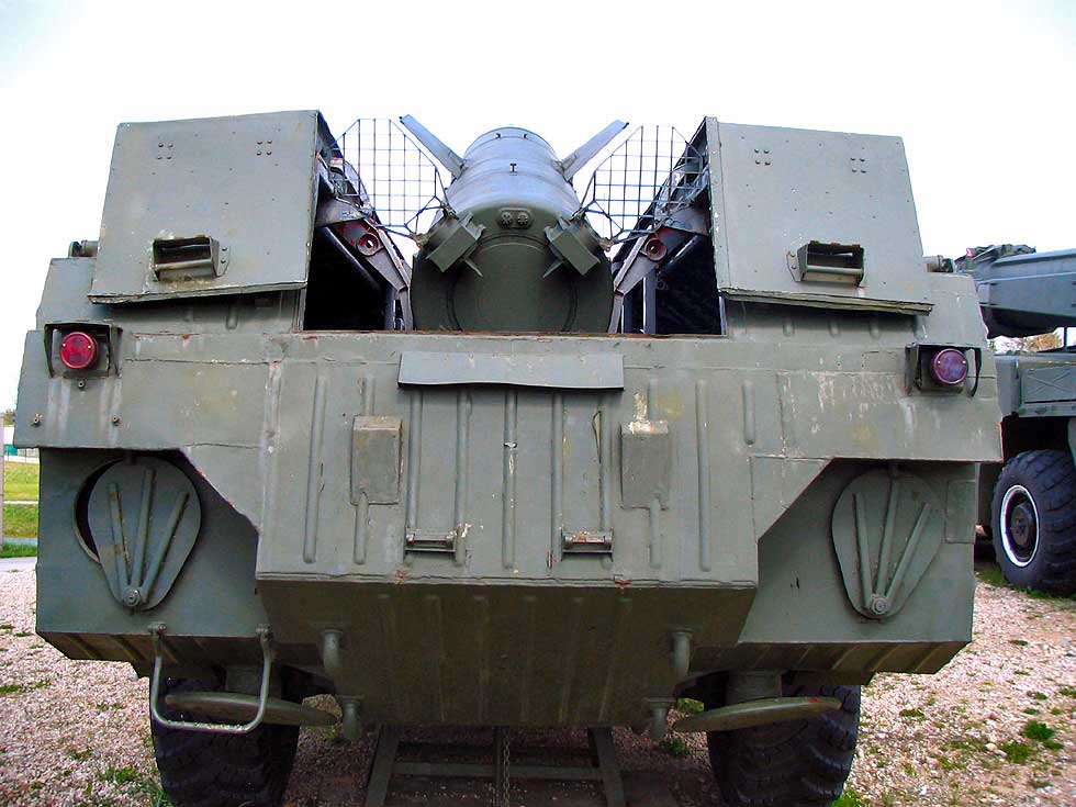
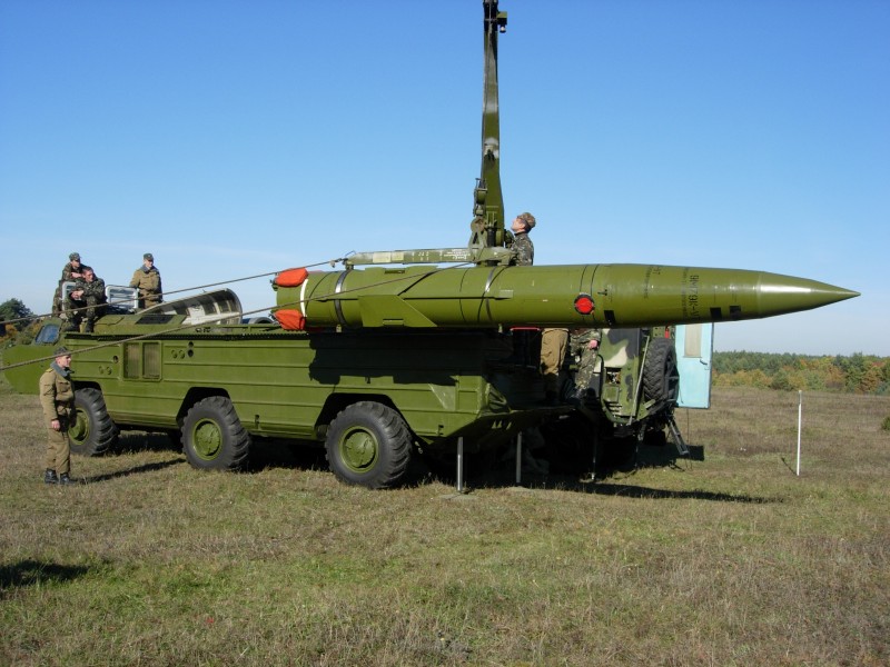
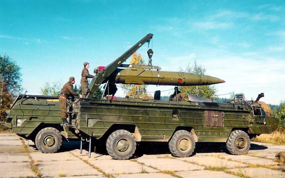
- Launchers: (see photo1, photo2, photo3, photo4, photo5, photo6)
- 9P129 (except for 9M79F-R) (9P129-1)
- 9P129M (9P129-1M)
- 9P129M-1 (see diagram)
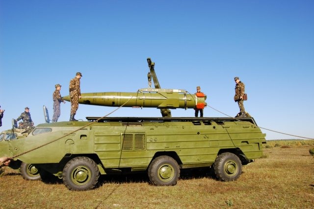
- Transport Charger (TZM) 9T218 (9T218-1) (see photo)
- Missiles:
- Special vehicles:
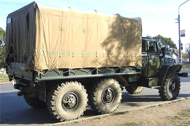
- Transport vehicles 9T238, 9T222
- Storage machines - special on-board machine of type НГ2В1 (НГ22В1)
- Containers
- 9J234 for the missile part and the missiles
- 9J236 for a combat unit
- Aerial Storage Carts
- 9T127, 9T133 for the missile part
- 9T114 for combat unit
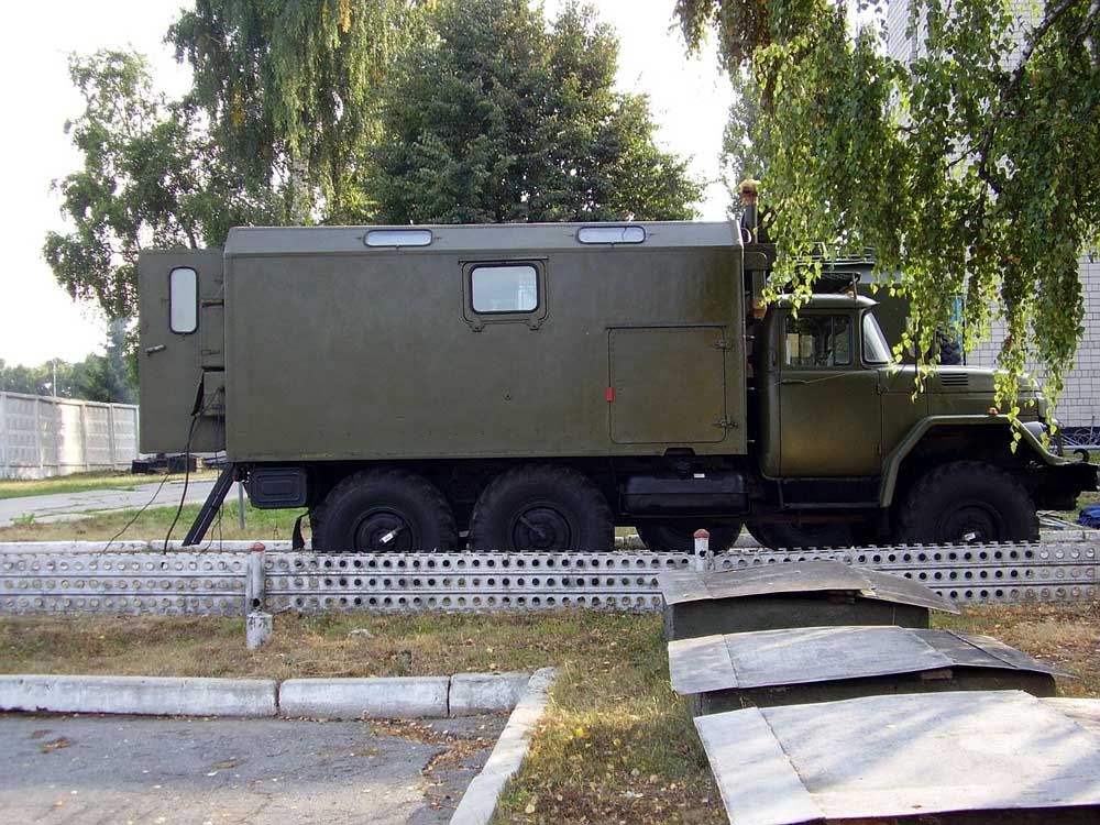
- Means of maintenance and regulatory work:
- automated control and testing machine AKIM 9B819 (9B819-1) for carrying out routine maintenance works with missile and combat units (except for special BC).
- maintenance machine МТО 9В844 - for checking the control and testing equipment of PU and AKIM units
- maintenance machine MTO-4OS is designed for repair and maintenance of the base part (four-axle vehicles).
- set of 9F370 arsenal equipment for routine maintenance work on bases and arsenals.
- Communication control means - command and staff machine R-145BM (R-130, R-111, R-123)
- Training aids:
- Training missiles 9M79F-UT, 9M79K-UT.
- Training combat unit - 9H39-UT, 9H64-UT.
- dimensional and weight model - 9M79-GVM.
- cutting model of the missile unit 9M79.
- Mock-up of the 9N123F-RM fragmentation fragmentation combat unit.
- A cut model of a cluster combat unit - 9H123K-PM.
- The simulators:
- 9F625 - complex simulator for training of PU calculations.
- 2U43 - simulator for control panel of mechanic-driver of starting installation.
- 2U420 - operator's simulator.
- 2U41 - simulator for training the correctness of taking the countdown from gyrocompass 1G17.
- 2U413 - simulator missile 9M79F, interaction of elements of the complex.
In addition to the listed equipment, the technical units are in service with cranes 9T31M1 and 8T311M washing-neutralizing machines and other equipment.
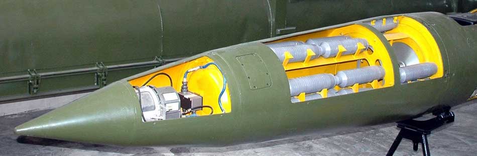
Rocket 9M79 (9M79-1)
The 9M79 (9M79-1) missile is a single-stage, guided missile and combat unit (see diagram).
The missile unit (RF) is designed to deliver the combat unit (BC) to the target and includes:
- Rocket body. The RF casing is designed to accommodate all RF elements. The RF casing is a power element that perceives loads acting on the missile in flight and during ground operation; it consists of:
- Instrument compartment casing (CFC). KPO is designed to accommodate individual devices of the control system and is made of aluminum alloy in the form of cylindrical shells with ribs. In the front part it has a bendscrew with 6 tilting bolts with self-locking nuts and 3 guide studs. At the front, the housing is sealed with a cover. In the lower part of the KPO there is a detachable connector for 205 (214) contacts, through which the electrical connection of SU devices with the ground control panel equipment PU is carried out, and also there is a transport bugle (for mounting the missile on the guided PU). On the right side of the KPO there is an illuminator (see photo) through which optical communication of the GSP with the 9P129 or AKIM 9B819 launch control devices is performed. On the upper left side there is hatch No.2 (in hatch No.2 in the ATP there is a key and a packet switch for fault input for educational purposes); next to hatch No.2 there is hatch No.3, where the plug connector of SCR37 is located, to which cable No.27 for temperature measurement inside a special BC on the TZM is connected.
There is a KPO inside it:- gyrostabilized platform (or gyroscopic command device) GSP 9B64 (9B64-1)
- discrete-analog computing device DAVU 9B65 (9B638)
- on-board automatic unit 9B66 (9B66-1)
- control unit 9B150 (9B150-1)
- sensor of angular velocities and accelerations DUSU-1-30V.
- Motor unit housings. The casing of the remote control is intended for placing and fixing a fuel charge and an ignition unit (igniter and two pyropatrons). It is a construction made of high-strength steel and has 3 bends - front, middle, rear. Two transport rods are attached to the front strap, and 3 launch rods are welded to the bottom of the front strap. There are 4 assemblies for attaching and fixing the air wings on the middle strap. On a back stanchion a transport bugle is fixed at the top, in the bottom part - 2 launch rods and one fixture for fixing of the rocket on PU and TZM, and also for holding of the rocket at lifting of a guide. On the inner side the case is covered with a layer of heat protection coating.
- Tailgate housings (CWC). The CWC is designed to accommodate the LC units and is at the same time a fairing of the RDTT nozzle block. The body is made in the form of an aluminum alloy cone with longitudinal stiffening ribs. For fastening and installation of aerodynamic and gas-jet steering wheels there are 4 fastening units on the rear part of the case. On the CWC in the lower part is mounted a descending sensor (closed with red removable cover, removable before loading). The off-set sensor is used to switch on the steering gear (start of the flight program). There are two hatches No. 11 and No. 13 on the upper part of the body for connection of hoses for the purpose of oil supply to the oil tank of the hydraulic system feeding, consisting of a pump, a tank and a switchgear, at carrying out of regular works by means of AKIM. In the lower part of the CWC there are two holes for gas outlet of the working turbo-generator power source (TGIP). On the outer conical surface and in the rear end of the case there is a layer of heat protection coating. Inside the CWC there is a layer of heat protection:
- hydraulic power supply unit 9B67 (refers to the steering) (9B639)
- gas turbine unit 9B152 (related to TGIP) (9B186)
- resistance block 9B151 (refers to TGIP) (9B189)
- regulator unit 9B242 (refers to TGIP) (9B242-1)
- 4 steering machines: 9B69 - top 2 pcs, 9B68 - bottom 2 pcs (9B89 - 4 pcs.)
- Aerodynamic surfaces. Aerodynamic surfaces - 4 aerodynamic rudders, 4 gas jets and 4 wings. Aerodynamic rudders control the rocket in flight on the entire trajectory. On the same shaft with them are gas-jet rudders made of tungsten alloy, which also act as the rocket control when the engine is running (see photo).
- Cable trunks. Two cable trunks are designed to locate cables for the purpose of connecting control devices located in software and CW.
- Instrument compartment casing (CFC). KPO is designed to accommodate individual devices of the control system and is made of aluminum alloy in the form of cylindrical shells with ribs. In the front part it has a bendscrew with 6 tilting bolts with self-locking nuts and 3 guide studs. At the front, the housing is sealed with a cover. In the lower part of the KPO there is a detachable connector for 205 (214) contacts, through which the electrical connection of SU devices with the ground control panel equipment PU is carried out, and also there is a transport bugle (for mounting the missile on the guided PU). On the right side of the KPO there is an illuminator (see photo) through which optical communication of the GSP with the 9P129 or AKIM 9B819 launch control devices is performed. On the upper left side there is hatch No.2 (in hatch No.2 in the ATP there is a key and a packet switch for fault input for educational purposes); next to hatch No.2 there is hatch No.3, where the plug connector of SCR37 is located, to which cable No.27 for temperature measurement inside a special BC on the TZM is connected.
- Motor setting (see description).
- Control system - autonomous, inertial, with on-board digital computer complex. The missile is controlled on the entire trajectory, which ensures high hit accuracy. When approaching the target for more efficient use of the BC explosion energy the missile performs a maneuver (turning the angle of pitch), which provides an angle of meeting the charge to the target close to 90 °. For the same purpose, the axis of charge of the 9H123F fragmentation-phase BC is deployed downwards against the axis of the hull of the head unit at a certain angle. In order to achieve the maximum area of impact, the 9H123F is exploded by air at a height of 20 meters.
- Onboard equipment of the control system 9B63 missile 9M79:
- 9B64 command and control gyroscopic device
- 9B65 discrete-analog converter
- hydraulic drive 9B616:
- automation unit 9B66
- hydraulic feeder 6B67
- steering unit top 9B68 - 2 pcs., steering unit bottom 9B69 - 2 pcs,
- turbo-generator power supply 9B149:
- control unit 9B150
- resistance block 9B151
- gas turbine unit 9B152
- controller unit 9B242
- angular velocity and acceleration sensor DUSU1-30V
- cable set
- Onboard equipment of the control system 9B84-1 missile 9M79-1:
- 9B64-1 command and gyroscopic device
- discrete-analog converter 9B638
- hydraulic drive 9B640:
- automation unit 9B66-1
- hydraulic feeder 6B639
- steering car 9B89 - 4 pcs.
- turbo-generator power supply 9B185:
- control unit 9B150-1
- resistance block 9B189
- gas turbine unit 9B186
- controller unit 9B242-1
- angular velocity and acceleration sensor DUSU1-30V
- cable set
- Onboard equipment of the control system 9B63 missile 9M79:
The missile is equipped with the following types of combat units:
- AA-60 - nuclear power from 10 to 100ct,
- The AA-86 is a nuclear one of particular importance,
- AA-92 - nuclear
- 9H123F - shrapnel-phase concentrated action (see description),
- 9H123K - cassette (see description),
- 9H123F-R - shrapnel-array with passive radar CNS.
The missile's combat unit does not separate in flight. The connection between the missile and the combat unit is carried out by 6 folding bolts with self-contained nuts on the ring connection, the electrical connection between the BC and the missile unit is carried out by a cable through the socket Sh45. The availability of interchangeable BC extends the range of application of the complex and expands its efficiency. Rockets in conventional equipment can be stored in a finally assembled form for 10 years. Assembly work with missiles in the troops is not required. When carrying out routine work is not required to remove devices from the rocket body.
In calculations of the flight mission when pointing the "Toch" at the target digital maps of the terrain, obtained from space or aerial photography of the enemy's territory are used.
Starting machine and transport charger
Main battle vehicles of 9K79-1 "Tochka-U" complex - 9P129M-1 launcher and 9T218-1 transport and charging machine.
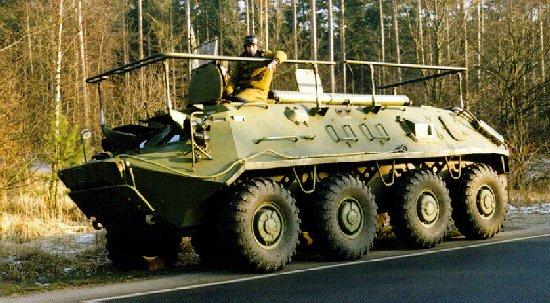
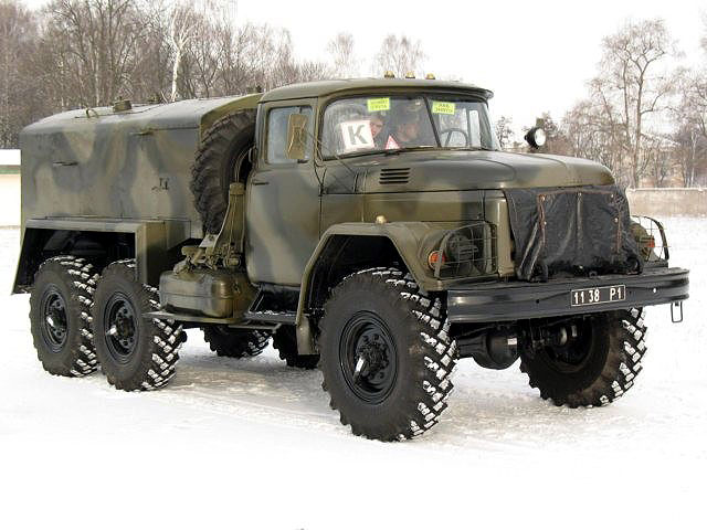
The launcher and the transport-charging machine are mounted on wheel chassis 5921 and 5922 of the Bryansk Automobile Plant. Both chassis are equipped with a six-cylinder diesel engine 5D20B-300. All wheels on the chassis are driving, tires are regulated by a centralized system of air pressure 1200 x 500 x 508. The chassis has a sufficiently large clearance of 400 mm. For movement on water there are water-jet propeller type pumps. The suspension of all wheels is independent torsional. Wheels of the first and third pair are controlled. On water, the chassis is controlled by flaps of water cannons and integrated into the body. Both machines are able to move on roads of all categories and outside them.
In addition to the 9T238 transport vehicle, the complex also includes the 9T222 transport vehicle. Externally, they are very similar and their transport possibilities are identical. Both of them are active road trains - i.e. semi-trailer bridges are the leading ones. The fundamental difference between these units in the way the torque is transmitted from the tractor to the trailer axles - in one case, the transmission is hydraulic, and in the other - mechanical.
Organizationally, the complex is a part of the FFM or TD, as well as in separate brigades (2-3 radars each), in the division - 2-3 starting batteries, in the battery 2-3 launchers ... The combat work is carried out on the move with a minimum of 3 people in the minimum time. Due to the presence in the PU system of topo-fixing, sighting, communication facilities, as well as life-support equipment for actions on contaminated terrain, the PU calculation can carry out missile launches from the cabin.
The 9K79 (9K79-1) missile system can be transported by AN-22, IL-76, etc. Missiles, missile parts and BC can be transported by helicopters such as MI-6, B-12, MI-8.
-
The equipment of the 9P129M-1 launcher solves all the tasks of linking the launch point, calculating the flight mission and aiming the missile. No top-geodetic and engineering preparation of launch positions and meteorological support during missile launches is required. If necessary, 16-20 minutes after the completion of the march and arrival at the position the rocket can start to the target, and after another 1.5 minutes the launcher is already able to leave this point to exclude the possibility of its defeat by a retaliatory strike. During aiming, on standby, and most launch cycle operations, the missile is in a horizontal position and its ascent begins only 15 seconds before launch. This ensures a high level of secrecy in preparing the impact from the enemy's tracking devices. In the cargo area of the launcher, a guideway with an elevation change mechanism is mounted, on which one missile can be transported. In the hiking position, the missile guidance system is mounted horizontally, with the cargo area closed from above by two casements. In combat position, the sashes are open and the guide rail is set at an elevation angle of 78°. The firing sector is ±15° from the longitudinal axis of the PU.
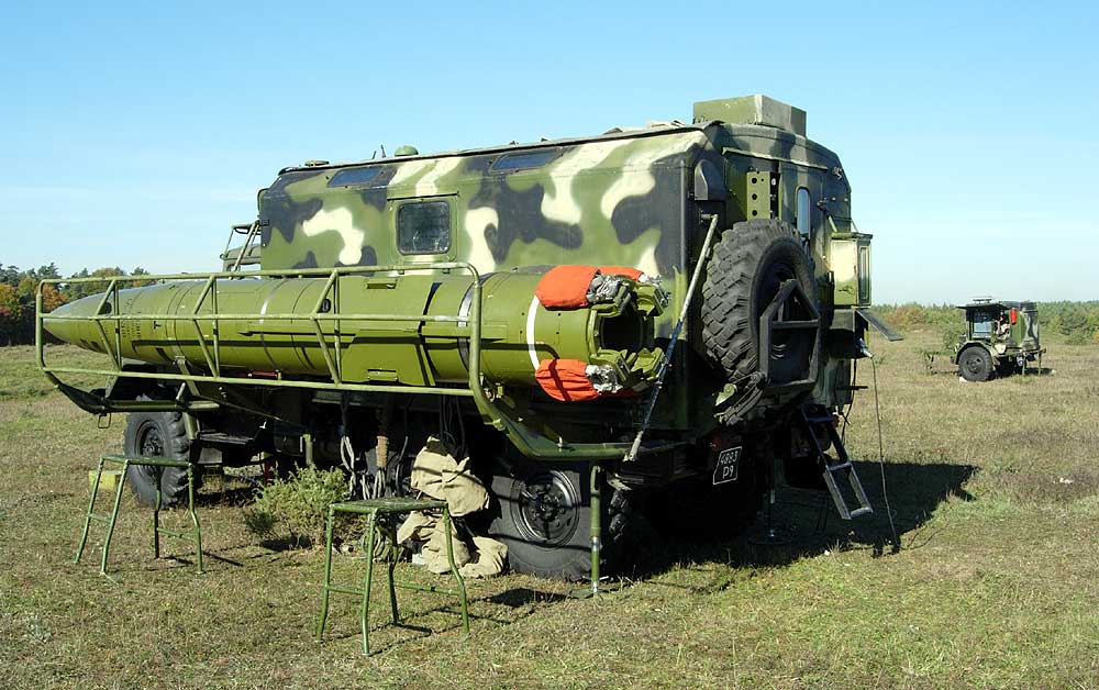
- Transport and charging machine 9T218-1 (TZM) is the main means of operational provision of starting batteries with ammunition for missile strikes. In its sealed compartment can be stored and transported through the combat area two fully ready to launch missiles with docked heads. Special equipment of the vehicle, including a hydraulic drive, a boom crane and some other systems, makes it possible to charge the launcher within approximately 19 minutes. This operation can be carried out at any unprepared in engineering respect site, the dimensions of which allow to put beside the sides of the launcher and the transport and charging machine. Rockets in metal containers can also be stored and transported on the transport vehicles of the complex. Each of them can accommodate two missiles or four head units.
Characteristics:
| 9K79-1 "Tochka-U" Missile Complex | |
| Year of adoption | 1989 |
| Developer | Kolomna Machine Building Design Bureau |
| Range of fire is minimal, km | 15 - 20 |
| Range of fire maximum, km | 120 |
| Missile trajectory altitude, km | 6-26 |
| Flight time at maximum range, with | 163 |
| Deviation of the missile from the target taking into account the error in determining the coordinates of targets not more than 100m and the launch point not more than 80m, m: - at a range of 35 km with BC 9H123F - at a range of 35 km with BC 9H123K - at a range of 70 km with BP 9H123F - at a range of 70 km with BP 9H123K |
165 210 200 235 |
| Launch preparation time from ready No.1, min. | 2 |
| Preparation time for launch from the march, min. | 16 |
| Start | 78 degrees inclined |
| Rocket 9M79-1 | |
| Number of steps, pcs. | 1 |
| Diameter of middles cross-section, mm | 650 |
| The length of the rocket, mm | 6410 |
| The length of the missile part, mm | 4085 |
| Wheelspan, mm | 1440 |
| Missile launch weight, kg | 2010 |
| Mass of the projectile part, kg | 1528 |
| Launching machine 9P129M-1 | |
| Weight of launcher (with rocket and calculation), kg | 18145 |
| Technical lifetime, km | 15000 |
| Crew, man. | 3 |
| Temperature range of operation, ha.C. | between -40 and +50 |
| Service life, years | at least 10, of which 3 years in the field. |
| Wheel formula | 6x6 |
| PU weight, kg | 17800 |
| Load capacity,kg | 7200 |
| Speed on land, km/h. | 70 |
| Speed afloat, km/h. | 8 |
| Power reserve, km | 650 |
| Engine | liquid-cooled diesel |
| Engine power, HP | 300 at 2600 rpm |
Testing:
During the demonstration of the Tochka-U complex at the IDEX-93 international exhibition 5 launches were made, during which the minimum deviation was several meters and the maximum deviation was less than 50 meters.
The Tochka-U complex was actively used by federal forces to destroy military facilities in Chechnya. In particular, the complex was used by the 58th Combined Arms Army to strike at positions of militants in the Bamut area. A large armory and a fortified terrorist camp were chosen as targets. Their exact location was determined by space reconnaissance assets.