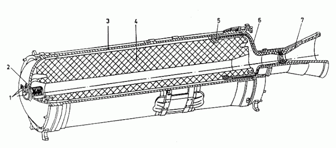
- 15X226 pyropatroons
- 9X249 ignitor
- motor casing
- fuel charge 9X151
- fuel cell
- back bottom
- nozzle block
The engine chamber is designed to place a fuel charge and convert the chemical energy of fuel into the kinetic energy of combustion products. It is made of high-alloy steel and consists of: front bottom, rear bottom with a nozzle (nozzle block), housing. An ignition system is mounted on the front ellipsoidal bottom. The nozzle block is mounted on the flange of the rear ellipsoidal bottom. The inside surface of the engine housing is covered with a thermal insulation layer. The nozzle block is designed to form a gas flow emanating from the nozzle. It consists of the body and a composite nozzle. The nozzle is sealed with a sealing plate. The body of the nozzle block is made of titanium alloy. Inlet and outlet of the nozzle is made of pressed materials such as graphite, silicon. In the critical section of the nozzle there are inserts made of silicylated graphite, while the inner surface of the insert is made of tungsten.
Fuel charge 9X151 (see diagram) is a chemical energy source, made of a mixture of solid fuel grade DAP-15B (a mixture of ammonium perchlorate with rubber and aluminum powder). The charge is made as a cylindrical monoblock. The most part of the external surface of the charge is covered with armouring (cotton cloth impregnated with non-combustible composition) - to ensure constant burning (constant burning area). There are annular ducts on the ends of the fuel charge, no armouring on the ends. During operation of the remote control, the fuel charge burns on the inner channel of the front and rear ends and the unarmoured outer surface. This fuel-charging design provides an approximately constant combustion area throughout the engine run. The charge is attached to the combustion chamber by means of a mounting assembly that is attached to the ring-shaped discharge of the charge on one side and clamped between the tail end and housing. The attachment unit consists of a rubber-coated textolite and a metal ring. It additionally prevents the flow of gases into the CW area through the ring gap between the remote control housing and the charge. From the start of the engine, the gases flow into the ring gap (circular) between the fuel charge and the casing, thus creating a dead space. In this dead space, the gases cool down quickly, which prevents the combustion chamber walls from burning (heating) and compensates for the internal pressure on the fuel charge.
The ignition system is designed to supply a fire pulse to the fuel charge. It consists of two 15X226 pyropatrons and 9X249 ignitor (see diagram). The safety type pyrotons are designed to activate the ignition. The igniter is designed to ignite a fuel charge directly and consists of a housing inside which there are pyrotechnic tablets and smoky rocket powder.
| Charge weight 9X151 with armour coating, kg | 926 |
| Weight of armour covering, kg | 17 |
| Circuit pulling force nominal, kgs | 9788 |
| Specific tractive force CRS, m/s | 236 |
| Average pressure in the remote control chamber, kgf/cm2 | 69 |
| Engine running time, s | 18.4-28 |
