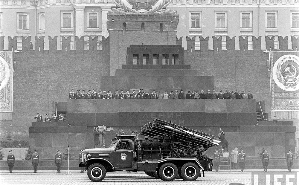
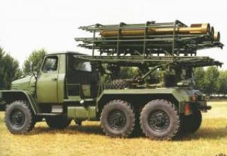
The BMD-20 combat vehicle is designed for firing 200 mm MD-20-F high-power blast rockets with a range of up to 19 km. Possessing high maneuverability and speed of fire, as well as the ability to fire volley shells of high power in a short period of time, the combat vehicle can be effectively used for suppression and destruction of enemy fortifications, strongholds and resistance units; destruction and suppression of artillery and mortar batteries; destruction and suppression of enemy manpower and equipment in areas of concentration. Military use is possible in mountainous environments.
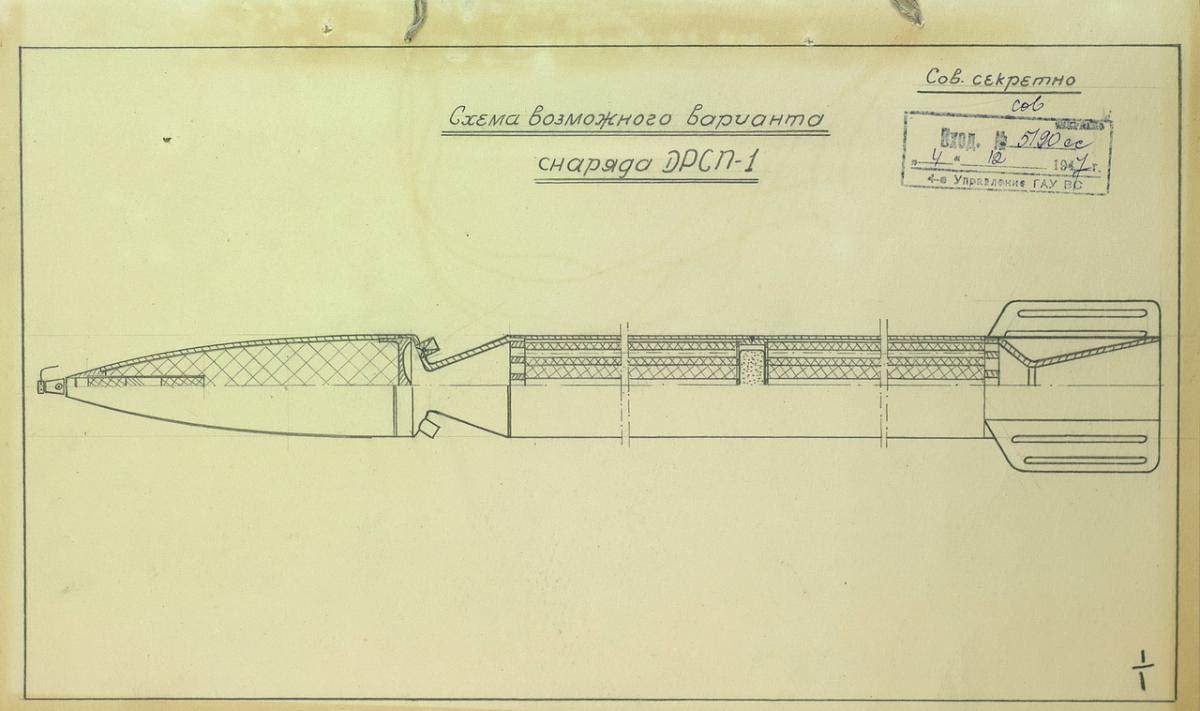
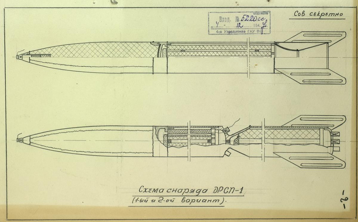
During development, the system was designated "DRSSP-1". The development was carried out on the basis of tactical and technical requirements №004 for the long-range missile system "DRSSP-1" by the 4th Directorate of the Main Artillery Directorate of the Armed Forces, approved by the Commander of the Artillery of the Armed Forces, Chief Artillery Marshal Voronov on 25.04.1947. In the course of initial work several variants of future projectile designs were considered (Scheme 1, Scheme 2), based on the data from the archives of CAMO RF dated December 4, 1947). One of the WSAE archival files also mentions data on two versions of the rockets. The design of the first variant included a rocket part consisting of a launching chamber with diagonal nozzles providing for the rotation of the projectile on its trajectory to ensure the reduction of the perturbation forces, and a traction chamber. The traction chamber and the launch chamber worked simultaneously. The second version was a single-chamber projectile with a telescopic powder charge. Structurally, the head part did not differ from the head part of the first variant.
The MD-20 system as a part of the BMD-20 combat vehicle and the MD-20-F projectile was developed in the SCB MOS under the leadership of V.P.Barmin. The system received the designation MD-20 and was adopted by the Soviet Army on the basis of the USSR Council of Ministers Decree № 4965-1936ss of November 22, 1952, the same day as the M-14 system.
For the first time a large elongation projectile with a single-piece solid fuel charge was developed for the rocket artillery system. The maximum range of the projectile under normal conditions was 18750m.
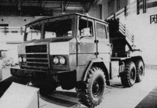
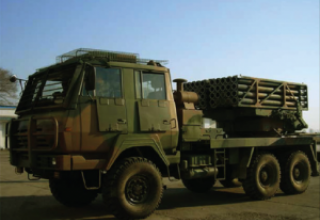
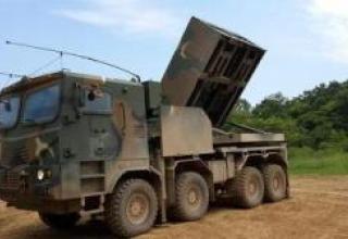
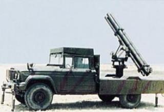
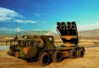
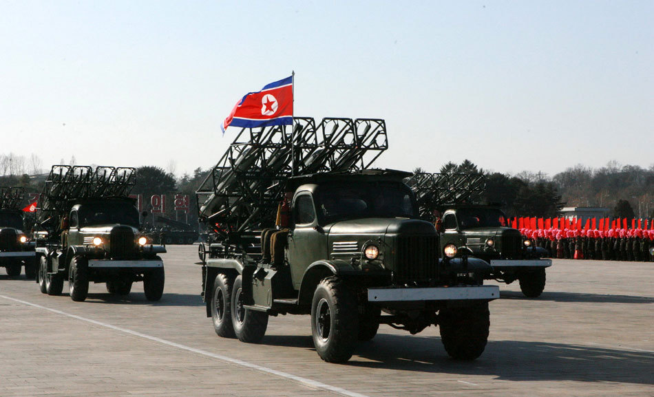
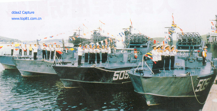
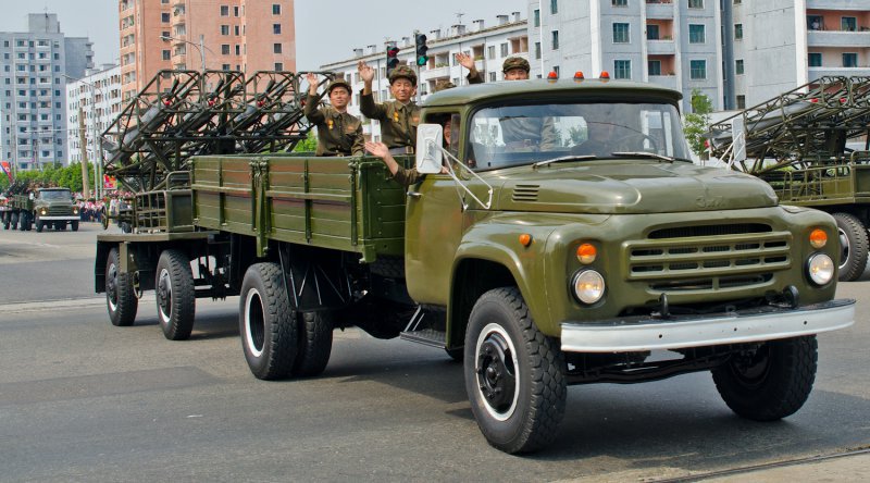
MD-20 was exported to North Korea, Ethiopia and possibly other countries. At least four BMD-20 combat vehicles were displayed during Kim Jong-il's 70th anniversary parade in Pyongyang, the capital of North Korea, on 16 February 2012 (see photo). Whether they are in service or were shown as rarities is unknown. No information is available regarding the projectiles. In North Korea, the guides used for the guidance package of the BMD-20 combat vehicle artillery unit are believed to have been used in the design of the sea-based multiple launch rocket launcher guidance system, which may have been in service with the North Korean navy (see photo), and for a towed mount on a modified trailer chassis (see photo).
Composition:
The MD-20 system is a part of it:
- BMD-20 combat vehicle (see schemes in camping position, combat position);
- the MD-20-F unmanned rocket projectile (see description) with the VD-20 fuse.
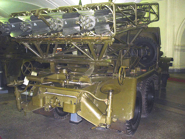
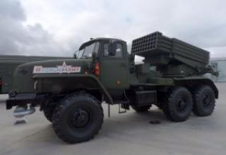
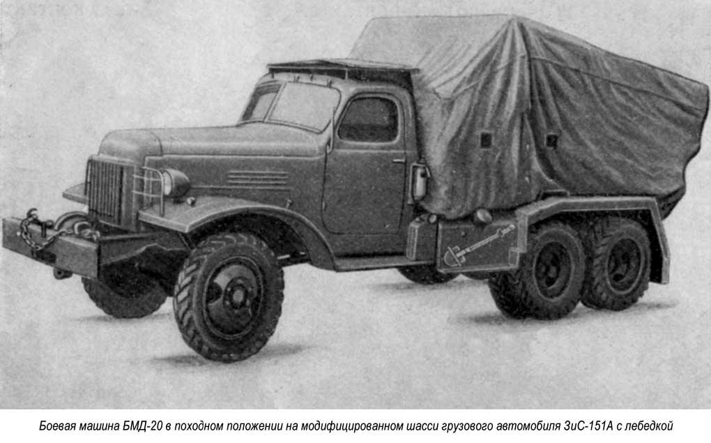
Fighting vehicle BMD-20 (8UZZ) with four rails is mounted on a car chassis. Modified chassis of ZIS-151, ZIS-151A and ZIL-151 trucks were used as a base.
The artillery part of the BMD-20 consists of four rails, a farm with a device for charging, turning frame, subframe, swivel mechanism, lifting and balancing mechanism, electrical equipment, sighting devices and special chassis equipment. The swivel frame is mounted on the stretcher and when rotated, it moves with its patches on the stretcher's patches. The stretcher serves as the basis for the artillery part of the fighting vehicle and is a welded rectangular frame, mounted on the spars of the vehicle chassis. The rotating mechanism is of screw type. The lifting and balancing mechanism consisted of a screw type lifting mechanism and a spring type pusher type balancing mechanism. The fighting vehicle rests on two rear jacks when firing.
The BMD-20 guide (see diagram) is a welded structure, consisting of four spiral longitudinal elements (one of them is a drive with a groove), fastened with four cages. A rigid frame of four longitudinal pipes and square bends is formed around each guide. The spiral elements of the guide are used to move the projectile when it is fired, with the projectile pin moving along the groove of the leading rod. Two stops are installed on the leading spiral rod of the guide to keep the projectile from moving forward and falling backwards when the oscillating part is lifted to an elevation angle. A contact device is mounted on the guide rod, which forms an electrical circuit with the rocket's candle contacts.
The guides are mounted on the farm. The farm was a spatial welded structure. It is installed in the bearings of the swing frame brackets and together with the guides it forms the oscillating part of the fighting machine. A charging device was installed on the farm.
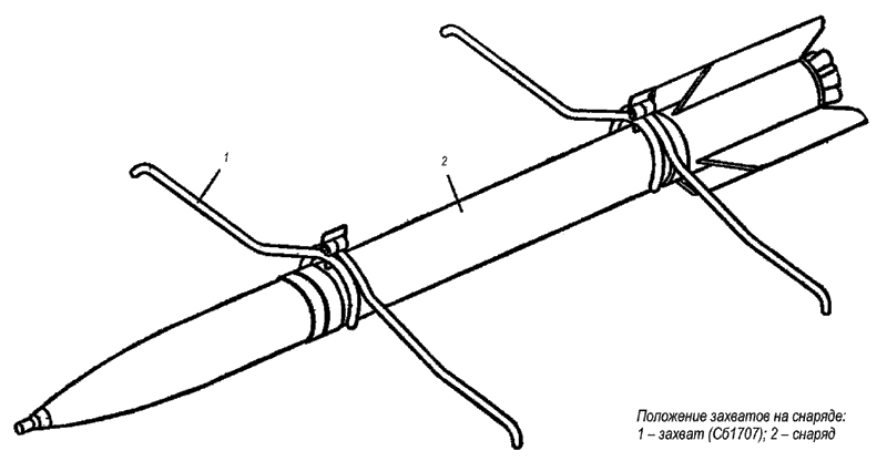
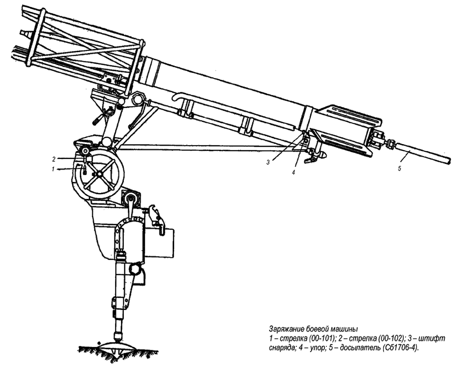
Charging is performed manually by five calculation numbers. When charging, the projectile is placed on a special tray using grippers (see diagram), then a rider is placed on the nozzles of the projectile, by means of which the projectile is riddled into the guide so that its driving pin is behind the rear stop (see diagram).
Characteristics:
| Maximum range of fire, m. | 18500 (18750) |
| Structural data: | |
| Caliber of guide,mm | 201 |
| Number of guides | 4 |
| Guide length, mm | 3160 |
| Largest elevation angle | +60° |
| Smallest elevation angle | +9° |
| Horizontal aiming angle | ±10° |
| Dimensional data | |
| The length of the fighting vehicle in camping position, mm : - without a winch - hoisted |
7210 7540 |
| Combat vehicle width, mm: - on the move - at gunpoint |
2300 2660 |
| The height of the fighting vehicle, mm: - on the move - overhang |
2850 4250 |
| Weight data | |
| Weight, kg: - loaded combat vehicle - armoured combat vehicle without shells and payload - artillery unit - guide - trusses with charging device - swivel frame - lifting and balancing mechanism - subframe - booster seats - cabin guards - jack |
8700 7455 2400 190 215 220 107 221 134 71 33.5 |
| Operational data | |
| Maximum time required to produce a full salvo, s | 6 |
| Time of transition from marching position to combat position (without recharging), min | 2 |
| The time it takes to charge a combat vehicle, min | 4-5 |
| Effort, kg: - on the flywheel of the lifting and stabilizing mechanism - tilt handle |
up to 10 up to 10 |
| Change of elevation angle in one rotation of the drive wheel of the lifting and balancing mechanism | 0°15' |
| Changing the swing angle in one turn of the rotary handle | 0°27' |
| Maximum speed of a loaded fighting vehicle on paved highway, km/h. | up to 60 |
| Maximum pulling force of the winch | 4500 kg |
| Highest ford depth with hard bottom overloaded by loaded combat vehicle, mm | 750 |
| Highest lift over a loaded combat vehicle in dry and hard ground | 28° |
Testing:
As of 01.01.1950, the factory batch of 230 shells was completed and sent to the Pavlograd test site.
In November 1949, pre-factory tests of 34 shells were carried out together with the fuse B-377 during which cases of missiles were revealed.
Special tests carried out to determine the causes of deficits showed that the most probable cause was an increased release of unburned reactive charge particles at the end of the active section of the trajectory.
In order to eliminate this phenomenon, in December 1949 a bench-top refinement of the engine was started with regard to aperture enhancement and ensuring that the powder charge was fixed in the chamber. After the end of the bench work and experimental firing for checking the reinforced aperture, the factory batch of projectiles was to be equipped with modified apertures on site and presented for factory tests in February 1950.
Sources:
- Носовицкий Г.Е. Продолжение “Катюши”. М.: Вузовская книга, - С.249.
- Боевая машина БМД-20 (индекс 8У33). Руководство службы. 2-е изд. М.: Воениздат, 1958. – С.3,117,119,155,156,141,142.
- Боевая машина БМД-20. Краткое руководство службы. – М.: Воениздат, 1953. – С.180.
- СССР.Парады (после 1945 г.)
- Горные таблицы стрельбы фугасными реактивными снарядами МД-20-Ф с тормозными кольцами. – М.: Воениздат, 1961. – С.3.
- РГАЭ. Ф. 334. Оп. 1. Д. 38. Л. 9-11.
- С П Р А В К А О состоянии на 1.1.1950 г. отработки опытных образцов реактивного вооружения согласно Постановлений Совета Министров СССР № 1175-440сс от 14.1У.48 г. и № 5766-2166 от 27.XII.49 г. / Дальнобойный реактивный снаряд на дистанцию боя 20-25 км (ДРСП-1) // РГАЭ. Ф. 334. Оп. 1. Д. 163. Л. 1,3,4. Завизированный документ. Подписи С.Бодрова нет.
- Щербаков Б.Ф. " Наземные оперативно-тактические ракетные комплексы: учеб.пос. БГТУ,СПб,2008г., 161с.
- Фото морской установки, присланное автору данной работы польским журналистом Томасом Шульцем (Польша).
- ЦАМО РФ. Ф.81. Оп.160821сс. Д.125. Л. 65-74об.
- ЦАМО РФ. Ф.81. Оп.160821сс. Д.126. Л. 1-2.
- ЦАМО РФ. Ф.81. Оп.173178сс. Д.435. Л. 49.
- Forecast International. – August 2001.
- Jane’s Armour and Artillery 1986-1987. – London: Jane’s Publishing Limited, 1988. – P. 764.
- URL: http://www.vokrugsveta.ru/news/13997/
- URL: http://x.limgs.cn/f1/g/120217/n20124707402014f3d93e4e498b.jpg
- URL: http://v.cn.yahoo.com/newspic/video/1686/27/
- URL: http://alerozin.narod.ru/KNDRiUSSR.htm
- URL: www.top81.com.cn
- URL: http://topwar.ru/61042-artilleriya-koreyskoy-narodnoy-armii-chast-3-reaktivnye-sistemy.html
