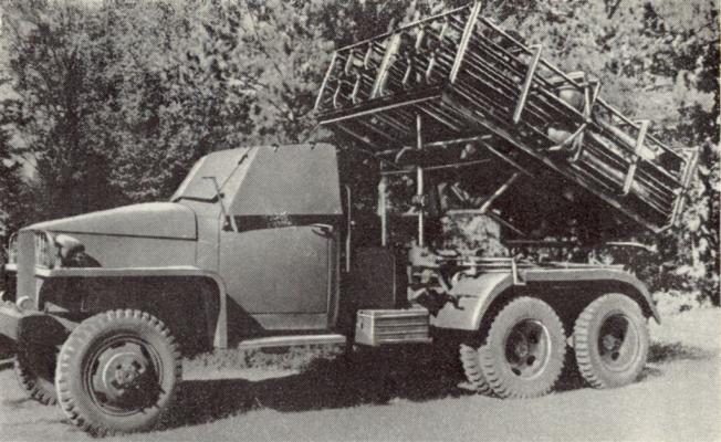
A significant achievement of the SKB specialists of the "Compressor" plant was the creation in March 1944 of a 12-charged combat vehicle with a throwing unit mounted on a modified chassis of the Studebaker truck, designed to launch the uncontrolled M-31 rockets of 300 mm caliber. It received the BM-31-12 cipher.
The distinctive feature of the BM-31-12 was the launch of unguided rockets not from the transport capping, but from a specially designed welded package - the so-called honeycomb guides. The design of the launcher included new technical solutions for the launch: blocking and stopping of the uncontrolled rocket projectile in the guide rail, fundamentally new electrical equipment and others. All this made it possible to dramatically improve the combat and operational qualities of the unit.
A special device was developed for locking the projectile on the guide rail during the movement of the combat vehicle, consisting of upper and lower cross bars with pads to secure the projectile in the front position in the camping position, two rear folding grids with plates and tensioning devices to secure the projectile on the side of the nozzle cut and a system of levers that allow to lower or lift the folding grids and thus stop or release the projectile. At the same time, this device served as a lock to prevent the projectile from spontaneous firing in the camping position.
Tests of the BM-31-12 with honeycomb guides to determine its combat efficiency, strength, stability in firing and marching position, ease of charging and maintenance, the correct placement of individual units and mechanisms were conducted in April-May 1944 and showed its high technical characteristics. The report of the range, in particular, noted that firing with BM-31-12 M-31 shells is possible and safe both when the shooter is in the cabin and outside. BM-31-12 is stable not only when the jacks are lowered, but also when they are raised.
The development of the 12-charged BM-31-12 with cellular guides was an important contribution to the development of rocket launching technology, because previously there was no such installation for launching uncontrolled rockets of such a large caliber. Its creation led to a significant increase in the effectiveness of missile weapons. Compared to the launchers, there was increased mobility, improved pockets of fire, and it was possible to shoot at a wide range of elevation angles (from +10º to 45º).
With the adoption in April 1944 of the BM-31-12, which until the end of the Great Patriotic War had been the main Guards mortar for the firing of 300 mm uncontrollable rockets M-31 (ballistic index 53-F-972) and M-31-UK (ballistic index 53-F-973), the stage of creation in the SKB of the plant "Compressor" machines and installations for the launch of NURS with the head units of increased power ends.
After the war the throwing unit was mounted on the modified chassis of truck ZIS-151.
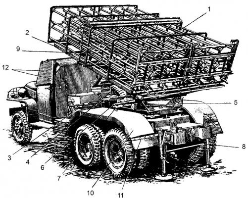
Composition:
General view of BM-31-12 (side view, in camping position):
- 1 - package of guide cells;
- 2 - a farm;
- 3 - pivoting mechanism;
- 4 - lifting mechanism;
- 5 - swivel frame;
- 6 - sighting console;
- 7 - sight;
- 8 - jacks;
- 9 - locking mechanism;
- 10 - fenders;
- 11 - bracket;
- 12 - cabin protection.
The fighting vehicle versions had the following differences:
The BM-31-12 combat vehicle subframe mounted on the Studebaker chassis differed from the BM31-12 on the ZIS-151 chassis by the fact that it was shorter by one section and did not reach the cabin, leaving room on the spars of the truck chassis to accommodate the gas tank.
The mechanism of the BM-31-12 on the Studebaker chassis differs from the BM-31-12 on the ZIS-151 chassis only by the fact that it lacked a folding handle. On the left end of the screw, instead of the extended folding handle, the ordinary handle was put on and fixed with a tapered pin.
The device to protect the cabin and gas tank, wings and fixing of the shank tools in the combat vehicle BM-31-12, mounted on the Studebaker chassis, was structurally different from the corresponding components of the combat vehicle, mounted on the ZIS-151 chassis, due to the design differences of both types of chassis.
Cab protection of the equipped truck chassis differed from the protection of the ZIS-151 equipped truck chassis only by the dimensions of the parts mating with the cab and the form of the locking device for mounting the shields on the road.
Due to the fact that the truck chassis Studebaker had only one gas tank and one spare wheel, the design of protection of the gas tank had the form shown in the figure. In this case, the spare wheel was attached to the right wall of the tank protection on two studs using two special nuts.
Wings 2 (see figure) of the equipped Studebaker auto chassis had rounded front and rear parts; they were less durable in operation than those of the equipped ZIS-151 auto chassis.
The chassis on the BM-31-12 combat vehicle on the Studebecker chassis was mounted as follows:
- a shovel and a saw on the back of the cab protection sheet;
- a pickaxe on the rear sheet of gas tank protection;
- an axe on the rear sheet of fuel tank protection.
Boxes for ZIP and for batteries of combat vehicle BM-31-12 mounted on the Studebaker truck chassis had the same design as the boxes of combat vehicle BM-31-12 mounted on the ZIS-151 truck chassis.
The combat vehicle BM-31-12, mounted on the modified Studebecker chassis for mounting the artillery part of the truck, when loaded in a camping position on a railway platform was beyond the rolling stock size "0" with the upper package of 210 mm and on the railways with the size "0" could be transported only with the wheels removed as an oversized cargo.
Characteristics:
| Basic data BM-31-12 (1944 data) | |
| Maximum range of fire | 4 km |
| Number of rails for simultaneous charging | 12 pcs. |
| The ignition of projectiles is carried out by electric ignitors one by one through the PUO. | |
| Speed of fire | 12 rounds of fire for 15-30 seconds |
| Required time for recharging | 15 min |
| Minimum elevation angle | 10° |
| Maximum elevation angle | 50° |
| Horizontal pointing angle with rotary mechanism | 10° |
| Total weight of combat vehicle in camping position | 5310 kg |
| Total weight of the combat vehicle in combat position / loaded/ | 6400 kg |
| Weight of the artillery unit | 2000 kg |
| Front axle load of the machine in charged condition | 1860 kg |
| Load on the front axle of the machine when it is not loaded | 1730 kg |
| Rear axle load in charged condition | 4500 kg |
| Load in uncharged state | 3580 kg |
| Combat vehicle length | 6,2 m |
| Width | 2,4 m |
| Height in hiking position | 3,2 m |
| Mark of the Studebaker car. | |
| Engine power | 95 PR |
| Petrol tank capacity | 140 litres |
| Consumption of fuel and lubricants per 100 km. track | 45 litres |
| Maximum speed of the car | 65 km/hour |
| M-31 blast projectile | |
| Basic data BM-31-12 | |
| Structural data | |
| Number of guides | 12 |
| Guide lengths, m | 3,0 |
| Largest elevation angle, deg. | +48 |
| Smallest elevation angle, deg. | +10 |
| Horizontal aiming angle, deg. | ±10 |
| Lifting crank handle force, kg | 10 |
| Turning handle force, kg | 8 |
| BM weight data (on Studebaker chassis) | |
| Weight of guide package, kg | 600 |
| Weight of the artillery unit, kg | 2000 |
| Weight of BM in camping position, kg | 5300 |
| Weight of vehicle in combat position, loaded with 12 shells, kg | 6400 |
| Dimensional data of the LM (on the chassis of Studebaker, in camping position) | |
| Length, m | 6,2 |
| Width, m | 2,4 |
| Height, m | 3,2 |
| Operational data | |
| Time to move from camping to combat, min. | 3-5 |
| The time it takes to charge the BM, min. | 10-15 |
| The time it takes to produce the salvo, s | 7-10 |
| Basic data BM-31-12 (revised chassis of truck ZIS-151) | |
| Number of guides, pcs. | 12 |
| Guide lengths, mm | 3000 |
| The highest elevation angle, º | +48 |
| The smallest elevation angle, º | +10 |
| Angles of horizontal aiming within, º | ±10 |
| Maximum force on the handle of the lifting gear, kg | up to 12 |
| Maximum force on the handle of the rotary mechanism, kg | up to 10 |
| Bag weight, kg | 700 |
| Weight of the artillery unit, kg | 2170 |
| Weight of combat vehicle in hiking position, kg | 7100 |
| Weight of combat vehicle in combat position (with 12 shells), kg | 8500 |
| Length in hiking position, mm | 7000 |
| Width in hiking position, mm | 2500 |
| Height in hiking position, mm | 3000 |
| Time to move from camping to combat, min. | 3-5 |
| The time it takes to charge a combat vehicle, min. | 10-15 |
| The time it takes to produce the salvo, s | 7-10 |
| Short technical specifications of cars Studebaker | |
| General data | |
| Load capacity of chassis, t | 2,5 |
| Number of driving axles | 3 |
| Fuel consumption per 100 km journey, kg | 30,4 |
| Traffic reserve when driving on the highway, km | 250-280 |
| Clearance, mm | 248 |
| Smallest turning radius, m. | 10 |
| Motor type | Hercules 4-stroke |
| Number of cylinders | 6 |
| Maximum power, HP. | 95 |
| RPM at maximum power, RPM/min. | 2500 |
| Voltage in the electrical equipment circuit, V | 6 |
| Tanks . | |
| Fuel tank, l | 150 |
| Cooling systems, l | 18,5 |
| Engine lubrication systems, l | 7.5 (with filter 7.62) |
| Used fuels and lubricants | |
| Fuel | Gasoline KV-70, B-70; leaded, motor gasoline with a boiling point not exceeding 220ºС. |
| Summer engine lubrication | Winter diesel oil; autol 10 (sulfuric acid or selective treatment); imported M-160 or M-30 oil. |
| Engine lubrication in winter | Lubricating; Autol 4 or 6 (sulfuric acid or selective treatment); imported M-120 oil |
| Adjustment data | |
| Deflection value of the fan belt, mm | 12-20 |
| Size of tires, dm. | 7,5×20 |
| Car tire pressure, atm. | 3,85 |
| Brake pedal free travel, mm | 12-15 |
| Clutch pedal free running, mm | 12-20 |
| The convergence of the front wheels, mm | 1,5-4,5 |
| Working order of cylinders | 1-5-3-6-2-4 |
| Oil pressure at warm engine average rpm, pound/inch 2 | 26 |
| Valve clearances when the engine is warm, mm | 0,15-0,18 |
| Spacing between candle electrodes, mm | 0,6-0,65 |
| Interrupter contact clearance, mm | 0,45-0,65 |
| Coolant temperature, ºF | 140-180º |
| Main data of the M-31-UK rocket (1944 data) | |
| Ballistics Index | ТС-52 |
| Caliber, mm | 300 |
| Outer diameter of rocket chamber, mm | 140 |
| Weight of final loaded projectile, kg | 93,5 |
| Weight of equipped head end, kg | 51,0 |
| Weight of explosive charge, kg | 27,5 |
| Weight of the rocket part, kg | 42,0 |
| Powder charge weight , kg | 11,15 |
| Length of projectile with fuse, mm | 1815 |
| Swing of stabilizer blades, mm | 300 |
| Rocket charge burning time, s | 0,9 |
| Average reactive force , kg | 2425 |
| Average projectile acceleration, m/s2 | 275 |
| Muzzle velocity of projectile, m/s | 35 |
| Length of active section of the trajectory, m | 110 |
| Highest projectile speed, m/s | 245 |
| Maximum projectile revolutions, revolutions per second | 15 |
| The longest range of fire, m. | 4000 |
| Funnel sizes in the middle ground / when installing the fuse on the "3" /: | |
| -diameter, m | 7-8 |
| -depth, m | 2-2,5 |
M-31-UK projectiles are placed in special wooden boxes, which are used for storage and transportation of projectiles and for firing from them.
| Weight and dimensions of the box | |
| Weight of the empty box, kg | 35 |
| Weight of the shell box, kg | 128,5 |
| Length of drawer, mm | 2130 |
| Box width, mm | 390 |
| Box height, mm | 415 |
Loading rate on M-31-UK projectile trucks
| GAZ-AA | ZIC-5 | JG-6 | Dodge | |
| Unrelated | 10 | 13 | 26 | 15 |
| Linked | 10 | 20 | 35 | - |
| Ammunition | ||
| М-31 | М-31-UK | |
| Caliber, mm | 300 | 300 |
| Stabilizer wingspan, mm | 300 | 300 |
| Full projectile length (without fuse), mm | 1760 | 1760 |
| Weight of final projectile, kg | 92,4 | 94,8 |
| Header type | blast | blast |
| Weight of rigged head end, kg | 52,4 | 52,4 |
| Weight of explosive charge, kg | 28,9 | 28,9 |
| Weight of the rocket part, kg | 39,6 | 42 |
| Powder charge weight, kg | 11,25 | 11,25 |
| Fuse | GVMZ | GVMZ |
| Resistance of incandescent bridge of electric ignition, Ohm | 1,0-1,4 | 1,0-1,4 |
| The current needed to ignite the igniter, A. | not less than 0.5 | not less than 0.5 |
| Ballistics data | ||
| Rocket charge burning time, s | 0,9 | 0,9 |
| Average reactive force, kg | 2500 | 2500 |
| Average projectile acceleration, m/s2 | 285 | 275 |
| Muzzle velocity of the projectile, m/s | 35 | 35 |
| The length of the active section of the trajectory, m | 115 | 115 |
| Highest projectile speed, m/s. | 255 | 245 |
| The longest range of fire, m. | 4325 | 4000 |
Testing:
It should be noted that 14 years after the end of the Great Patriotic War, in the course of work on the development of the projectile engine for "remote mining", in his letter (out. 5/V 59) to the Director of Research Institute-582 State Committee of the Council of Ministers of the USSR on Defense Technology, Comrade S.I. Chichkov. (Balashikha 1, Moscow region), Deputy Director of Research Institute-147 (now FSUE "SNPP" Splav "(Tula) Alexander Nikitovich Ganichev reported: "...I recommend for the variant of an optic non-rotating projectile to use the launch rails for the projectile M-31 /BM-31-12/ which requires the diameter of the cassette to change to 300 mm".
Sources:
- Боевая машина БМ-31-12. Руководство службы. Воениздат Министерства Вооруженных Сил Союза ССР. - М.: 1947. - С.4-6,61-63,96,97.
- Боевая машина БМ-31-12. Руководство службы. Воениздат Министерства обороны Союза ССР. - М.: 1955. - С.18,65-68,75,114,115.
- Боеприпасы Гвардейских минометных частей. Краткое руководство. Издание второе. ГАУ ВС Союза ССР. - М.: Воениздат, 1948. - С.14,16,17.
- ГАТО. Ф.Р3428. Оп.1. Д.448. ЛЛ.52,73.
- Ракетные пусковые установки в Великой Отечественной войне. О работе в годы войны СКБ при московском заводе “Компрессор”. // А.Н. Васильев, В.П. Михайлов. – М.: Наука, 1991. – С. 75–76.
- РГАСПИ. Ф.644. Оп.1. Д.263. Л.34.
- ЦАМО РФ. Ф. 12722 (2ГМД). Оп. 1. Д. 31. Л. 106,108,138,141,142,146.
