
The development of the operational-tactical missile system (OTRC) 9K76 "Tempe-S" with missile 9M76 was started by the USSR Council of Ministers Decree № 934-405 of September 5, 1962. The development of the complex was carried out by NII-1 (Chief Designer - A.D. Nadiradze), which by that time already had a solid foundation, obtained in the course of development and testing of the 9K71 "Temp" missile defense system. The control system was developed in NII-592, solid fuel engine charges in NII-125 (Lyubertsy). The starting unit of the complex was designed at the Design Bureau of Volgograd Plant "Barrikady". Avanproject of "Temp-S" Design Bureau was approved on December 13, 1962.
Flight and design tests of the missile began in 1964. The first launch of the 9M76 missile was made on March 14, 1964. The rocket flew 580 km. Of the first five launches, two were emergency. The fifth launch was held July 18, 1964, the rocket flew 850 km with a range deviation of 3.55 km and left - 3.44 km. In 1966, complex 9K76 "Tempe-S" was adopted for service.
Production of missiles 9M76 was conducted at plant number 235 in Votkinsk. In 1970 it was produced 100 missiles, in 1971 - 90, in the first half of 1972 - 50 missiles. The launcher was produced at Petropavlovsk Heavy Engineering Plant.
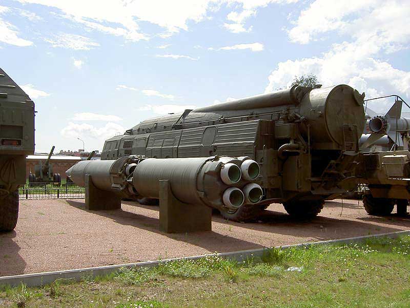
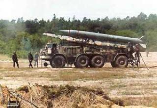
Complex 9K76 "Temp-S" mobile all its elements are installed on wheel chassis with high cross-country ability. The complex can be transported by rail, water and air without additional disassembly. The 9K76 divisions were at the disposal of the front command.
In the mid-60s, a modification of the "Temp-SM" rocket was designed, which was increased to 1100 km range and greater accuracy. There are no data on the adoption of the Temp-SM missiles.
After signing an agreement on the reduction of the RSMD in 1987, the Temp-S complex was removed from service and eliminated. The first 9M76 missile was eliminated on August 1, 1988, and the last of the 718 missiles produced was destroyed on July 25, 1989.
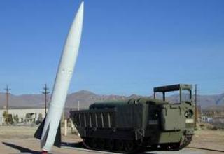
In the west, the complex was designated SS-12 SCALEBOARD mod.1 mod.2.
Composition:
The complex 9K76 is part of the complex:
- missile 9M76,
- sets of ground equipment for technical and starting positions.
Set of ground equipment of technical position:
- transport vehicle 9T215 to transport missiles,
- transport vehicle 9T219,
- 9T35 crane,
- Test and Start Machine (Test and Start Machine) 9B243,
- autonomous testing machine (IAI) 9B476,
- storage machine HC 9F21M,
- a tent with a benzoelectric unit and an air heater.
Set of ground starting position equipment:
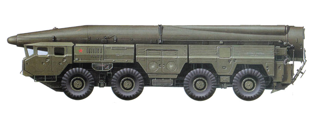
- 9P120 launcher with 9M76 missile (see layout diagram),
- testing and start-up machine 9B243,
- GAZ-66T topogeodetic binding machine.
The basis of the complex is a solid-propellant two-stage missile 9M76, which as a combat load carried a special charge of 300 kt (and in this case had the index 9M76B) or chemical warfare unit "Tuman-2". The missile is equipped with an autonomous inertial analogue control system with a gyrostabilized platform (GSP). It should be noted that the 9M76 was the first of the operational-tactical missiles equipped with the GSP.
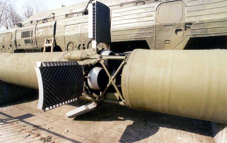
The missile is controlled by rotary nozzles. In the tail of the second stage there are folding lattice type stabilizers (photo). Separation of stages - "hot", ie, the second stage of the missile is launched while still working first, the command to separate the stages is given from the overload sensor. Program change of the pitch angle is set in GSP 9M76 mechanically (as well as in the gyro horizon of 8K14 missile) by means of a cam mechanism. Range control is carried out on the basis of reaching a given speed by the missile, which is measured with the help of a gyro-integrator of longitudinal accelerations, from the GSP. At the command of the gyro-integrator at a certain point of time the thrust of the second stage engine is zeroed by opening special cut-off units of the thrust with the help of pyroloads. To reduce the dispersion of the effect impulse, the second stage engine is shut down in two stages: first, two nodes of the cut-off of four are opened, then the engine switches to a lower thrust, and then, with some time delay - the remaining two nodes of the cut-off "turn off" the engine (zero thrust) finally. Then there is a separation of the head unit and it continues its independent flight to the target on a ballistic trajectory.
Control of correctness of gyrointegrator of longitudinal accelerations on the ground is carried out during the general tests and regulation works of the control system. In this case accuracy of determination of free-fall acceleration by the gyro-integrator is checked. And if during the general tests in the vertical position of the rocket there were no problems with this, then during the routine works in the horizontal position of the rocket it was necessary to deploy the gyrointegrator at 90°. For this purpose, the HSP of the 9M76 missile was mounted in an instrument compartment on a hinge. If necessary, horizontal testing was performed by unhooking the head end and turning the gyrostabilized platform on a 90 ° joint. The acceleration of gyroscopes of HSP was carried out in preparation for launch from a ground source. After firing the cable mast before the start, the gyroscopes were no longer powered and they continued to rotate by inertia. This solution slightly worsened the accuracy of the firing, but made it possible to abandon the onboard high-frequency converter and led to a significant simplification of the missile's electrical circuitry. The onboard power source was an ampoule battery. Non-standard for operational-tactical missiles, connecting the equipment to the rocket board using a cable mast, which is connected directly to the instrument compartment and tilted at launch, allowed to refuse to lay the cable through the connection of rocket stages and contributed to the reliability of the complex.
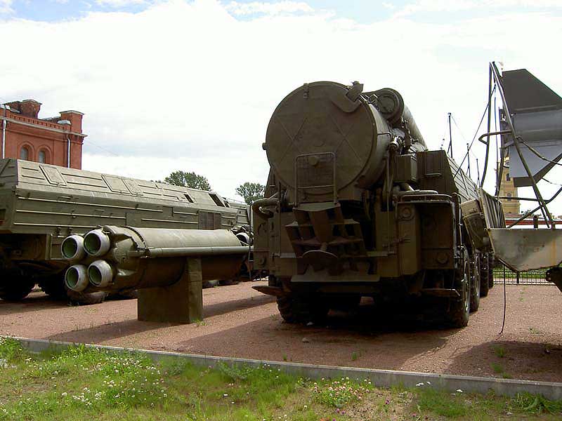
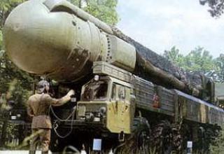
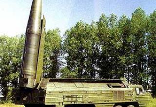
Launching unit 9P120 was mounted on a self-propelled chassis MAZ-543A of high cross-country ability, with the wheel formula 8x8. On the chassis there were: a container with rocket mounting mechanisms, drives for opening and closing the roof, the launch table with azimuth guidance mechanisms, gas reflector. On the starboard side of the compartment are placed auxiliary equipment, a set of ZIP. On the frame of the machine in the rear part there are studded units of container turning, starting table and gas deflector. Container lifting drive, starting table lifting drive and its longitudinal horizon, two jacks of hanging and transverse horizon drive are also installed there.
Electrical equipment PU provides operation of all its drives, heating the rocket and ventilation of the container, internal and external communication, lighting PU, heating and ventilation of the car cabins. Sources of power supply are diesel generator installed in the left side cabin, electric generator driven by the vehicle engine, chassis starter batteries. An external power supply of 26-30V can be connected to the PU.
To ensure constancy of the solid propellant charge physical properties, the missile was transported in container 9Y230 equipped with RDTT charge heating system. It was not allowed to "freeze" the rocket, i.e. to find it for a long time in conditions of low temperatures. The temperature during the missile operation was controlled by a special gyrostabilized platform assembly. The design of this unit included: a base with a hole, a ball of slightly larger diameter and a control window. The ball and base were made of materials with different thermal linear expansion. At the boundary temperature, the ball fell into the hole and this indicates that the missile was "frozen" and was not subject to further operation.
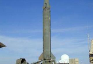
The rocket was lifted vertically in a container, after which the container was opened and placed on the launcher, and the rocket remained on the launch table, which when closed, the container served as an end cover (photo). The onboard equipment communicates with the prelaunch instrumentation via a cable mast. When the missile is installed on the booster, the lower cable mast attachment is connected to the launch table bracket, which ensures its separation from the missile during launch. Aiming at the target was carried out by turning the missile on the launcher table towards the target.

At the supply station (arsenal) the missile part (RF) (docked first and second rocket stages) is loaded by crane 9T35 on the transport machine 9T219. Similar operations are performed with the missile's head end. The RF is loaded into the 9F21M storage vehicle in its own container.
Transport vehicle 9T219 is mounted on the basis of MAZ-543, the chassis of which is equipped with a front support and podtsapfennoy beam at the rear of the frame of the machine. There is a platform on the chassis, on which a container with folded wheels for transportation is installed by crane. The container provides protection of the missile part from mechanical influences, climatic factors, and is covered with thermal insulating material from inside. After unloading the missile, the container is to be returned to a supply station or arsenal.
Crane 9T35 is designed to carry out all lifting, handling and installation and docking work at various stages of preparing the missile 9M76 to launch. Boom crane, full-circle, with hydraulic drive of power mechanisms, lifting capacity of 16 tons, mounted on the chassis of the vehicle MAZ-537K.
The 9F21M as a running gear uses a three-axle cross-country vehicle ZIL-167E, which has a metal thermo-insulated body, equipped with a heating and ventilating unit. On the floor of the body there is a special device that provides loading and unloading of the HF container and its fixation during transportation. The device consists of a rail track, a sliding ramp and a trolley.
After loading the machines 9T219 and 9F21M are moved to the technical position (TP). For the technical position is chosen a solid flat ground with dimensions 100x50m, with a slope not exceeding 2° with the possibility of access of vehicles. A tent with lighting and heat for the work of the personnel is installed at the technical position in advance.
Before the horizontal inspection of the RF crane 9T35 is loaded from the container 9T219 to the transport vehicle 9T215 on the chassis of the vehicle with high cross-country ability MAZ-543. The vehicle is equipped with a heated container, which accommodates the RF or a fully assembled rocket. The container is airtight, the rear cover is closed, the temperature required for storage of the rocket is provided by a heating system powered by a diesel-electric unit.
After loading the RF transport vehicle 9T215 enters the tent, and outside the tent is placed an autonomous testing machine 9B476 and a machine for testing and launching 9B243, which are connected by cables to 9T215 and on-board equipment RF. At this stage, the RF is prepared for joining it to the RF, complex tests of the RF on-board equipment and, if necessary, autonomous tests and replacement of its units are performed. The 9B476 autonomous testing vehicle is designed for autonomous testing of rocket instruments and is based on URAL-375A vehicle with KUNG-1M type covered body, inside of which there are control equipment, power supplies, operators' workplaces, heating, ventilation and lighting devices.
The testing and launch vehicle is designed for pre-launch preparation and launch of the rocket at the launch position (SP) in it was located all console equipment of the complex. MIP together with the MAI is involved in horizontal testing of the TP. MIP is based on the URAL-375A vehicle with an extended frame, differs in the presence of an electric generator operating from the PTO, an additional fuel tank for 300l. This vehicle is equipped with testing and launching equipment, power sources, a set of sighting devices (spetsteodolit, sighting rod, gyrocompass, levels for the verticalization of the rocket, etc.), operator workstations. Simultaneously with the preparation of RF in the tent at a special point of the technical position of the MS is removed from its container, checked and prepared for docking with the RF.
Upon completion of the checks in the tent, the 9T215 transport vehicle will carry the RF to the point of connection with the MS, where the docking operation is performed using the 9T35 crane. Before docking, the container from the transport machine is lifted to an angle of +8°, its roof is opened, the back cover is lowered, special rails - catchers are installed in the container. After the HC is overloaded into the container of the transport machine is docked to the RF. Such operation can be performed in the PU container as well. If there is no need to immediately start the rocket in the collected state is stored in the transport machine container. If necessary, the launch of the rocket is reloaded into the container PU 9P120.
The rocket is launched from the starting position (SP), which selects a solid platform size 40h20m with a slope of no more than 2 ° (see the scheme of the location of the missile system units at the starting position). With the help of navigation and top-geodetic equipment installed on GAZ-66T, geographic coordinates of the launch position are determined and its marking is made. It includes fixing the main and control geodetic directions (OGN and KGN) and the PU direction of arrival by means of electric motors and spetsteodolite. After that PU and MEPs enter the JV according to the layout and are transferred to the combat position. MEPs were placed on the right side of the launcher and connected to the missile through the cable network of the launcher. From the MIP panel, the missile was checked and the flight task was entered into the missile control system. Sighting devices - levels for verticalization of the missile and azimuth aiming bar - were installed on the launch table. These operations were performed by PU drives. After aiming, the rotating part of the launch table is fixed, and the sighting devices are removed from the PU and transferred to the MEP. The spetsteodolite and milestones are removed, the personnel are withdrawn from the danger zone, and the command for the launch is given from the remote control.
When the "start" button is pressed on the remote control, the on-board power supplies are initiated, their normal operation is checked and then the first stage RDTT is activated. When the missile is detached from the launch table, a tie strip holding the stabilizers is opened, the cable mast connectors are disconnected from the instrument compartment, and it is pushed away by a spring pusher from the missile body.
The operating instructions of the complex provide for several degrees of readiness:
- N1 - the whole scope of pre-start preparation was completed. Ready time from 15 minutes to 2 hours.
- N2 - the missile is in the PU container in horizontal position. Launch time - 20 min, duty time up to 1 year.
- N2a - the missile is in the PU container in the vertical position, the launch table at the bottom is covered with a thermal cover. Duty time - 6 months.
- N3 - the missile system is in a camping position near the starting position. Launch time - about 25 min.
Characteristics:
| Range of fire, km | 900 |
| KVO, m | 3000 (2000) |
| Number of steps | 2 |
| Length, mm | 12380 (12780) |
| Maximum diameter, mm | 1010 |
| Start weight,kg | 9300 |
| Weight BC,kg | 530 |
| Weight of charges RDTT,kg | 6880 |
| Chassis | MAZ-543A |
| Length PU, mm | 11490 |
| PU width, mm | 3050 |
| Engine | D12A-525A |
| Power, HP. | 525 |
| Fuel reserve,l | 520 |
| Smallest turning radius, m. | 13.5 |
Testing:
In the mid-1960s, in order to study the impact of aggressive propellant components on the missile during its long-term operation, on the initiative of V.N.Chelomey at the test base in Faustovo were built two mine launchers for missiles 8K84. One of the silos was manufactured in the standard version and was intended for research of the standard missile during the entire warranty period of its storage. This mine also contained more than 1000 samples of materials - metals, non-metals, rubber goods, adhesive and welded joints of various shapes and combinations, radio equipment, pumps, batteries and much more. In addition to the employees of OKB-52 more than 100 related enterprises participated in the research of materials resistance to long-term storage. Simultaneously, several times a day for the duration of many years of storage about 100 parameters (temperature, humidity, gas content, pressure in tanks, etc.) were registered. The second mine was also designed for the 8K84 missile. The rocket installed in it was filled with aggressive components and stored at a temperature of + 50 degrees for accelerated corrosion tests within one year. During the experiments, no serious malfunctions or failures of rocket systems were detected in any of the mines. The results of these tests extended the warranty period for subsequent modifications to 15 years, then to 20 years, then to 25 years.
Sources:
- Дудин С.М. 'Устройство подвижной пусковой установки "Темп-С": учеб.пос. БГТУ,СПб,1999г., 44с
- Щербаков Б.Ф. " Наземные оперативно-тактические ракетные комплексы: учеб.пос. БГТУ,СПб,2008г., 161с
- Оперативно тактический ракетный комплекс "Темп-С" 9К76 SS-12 "Scaleboard", SS-12M "Scaleboard-B" /http://www.kapyar.ru/
- Форум 11-ой гвардейской танковой
