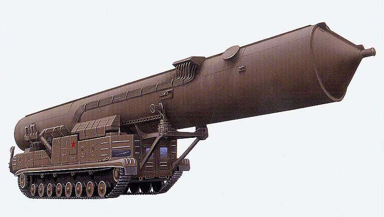
The development of a mobile ground-based missile system equipped with an intercontinental ballistic missile (ICBM) began at Yuzhnoye Design Office (Dnepropetrovsk) in 1964. The first version of the RT-20(8K99) ICBM was a three-stage solid-fuel missile. During the next stage of design work to reduce the launch weight of the missile it was decided to develop a two-stage RT-20P with the first stage equipped with a solid propellant rocket engine, and the second stage with a solid propellant engine. This decision was taken due to the fact that the missile was mounted on a mobile tracked self-propelled unit on the basis of the T-10M tank (project 821), which could not transport a missile with a mass of more than 30 tonnes.
Officially, the development of the complex was set by the Decree of the USSR CM of August 24, 1965. In 1966 the conceptual design of the 15P699 mobile complex was carried out.
The self-propelled launcher was designed by the Design Bureau of Mechanical Engineering (Chief Designer - B.G.Bochkov), the solid propellant engine of the first stage was developed by the Design Bureau of Mechanical Engineering (Chief Designer - M.Yu. Tsyrulnikov), the charge designer - by the Research Institute-130 (Chief Designer - L.N.Kozlov). Simultaneously with the main variant of missile deployment in the KBM, several mine-based variants of the RT-20P ICBMs were under development.
Flight testing of the missile began in October 1967 in Plesetsk (Technical Test Manager V.S.Budnik). There were 12 test launches, after which in October 1969 the USSR Council of Ministers issued a decree on termination of work. The reason for the termination of work was the complexity of operation of the mobile complex with liquid rocket engine on the second stage, as well as the lack of a state program for its placement in the country.
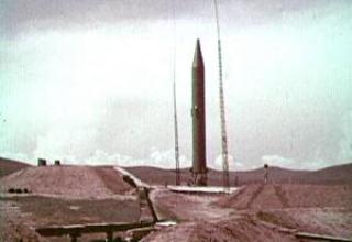
The complex was first demonstrated at the military parade in Moscow on November 7, 19665.
The complex was designated by NATO SS-X-15 "Scrooge".
Composition:

The complex 15P699 was part of the complex:
- Six SM-SP21 self-propelled PU with RT-20P(8K99) missiles;
- war control machine 15H809;
- two preparation vehicles for position 15N1034;
- two 15P694 diesel-electric power plants;
- communication center "Relief".
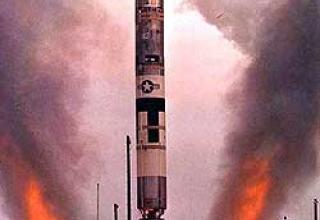
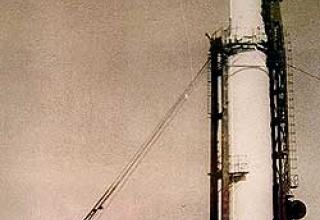
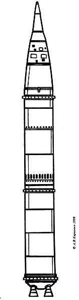
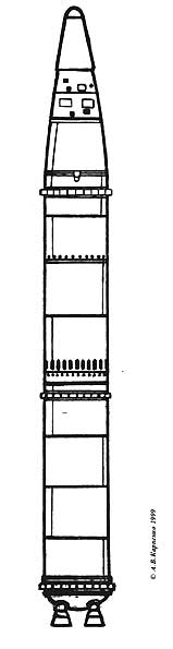
The 8K99 missile was supposed to be used in two versions: with light (see Figure 1) and heavy (see Figure 2) head units. The head units are monoblock and thermonuclear. The "light" head part had a body made as a set of three truncated cones with spherical dullness. To reduce aerodynamic drag, the "light" head end had a tapered fairing that was dropped during the second stage engine operation when the rocket reached the discharged layers of the atmosphere. The head end was attached to the upper docking sleeve of the instrument compartment using three breakaway bolts. Three thrust reversing motors were used to separate the head end from the second stage of the missile.
In the case of the "light" head part, the instrument compartment has the shape of a truncated cone and the "heavy" head part has a cylindrical shape. The main part of the rocket control system instrumentation is located in the instrument compartment. The 8K99 missile control system is an inertial, autonomous one with air-suspended gyro devices (weight SU 250 kg) and a high-speed digital computing machine. Communication of the onboard equipment with the launcher is carried out by means of two blocks of connectors, one of which is located on the side surface of the instrument compartment housing another - on the container. Before the rocket leaves the container, the connector block of the container is separated by means of breakaway bolts and repelling springs. After the missile leaves the container, the connector block of the missile is separated in the same way. The remaining part of the block on the missile is closed with a lid. The instrument cluster is bolted to the upper end end sleeve of the fuel cell.
The fuel cell is a container divided by an intermediate bottom into two cavities: the upper one for oxidizer and the lower one for fuel. As an oxidizer nitrogen tetraoxide is used as a fuel - asymmetric dimethylhydrazine (NDMG) To the lower end-frame of the fuel cell with a rod frame is mounted liquid rocket engine 15D12 second stage. Control of the second stage on the corners of the pitch and yaw is carried out by an inflatable turbo-gas in the critical part of the engine nozzle. Two pairs of tangentially installed control nozzles, which also use turbogas, are used to control the heel.
Stage separation is "hot", i.e. the breaking bolts trigger after the second stage engine unit is started. There are windows in the shell of the transition compartment that provide gas exit at the initial stage of the separation process. Collision of the transitional compartment casing with the second stage engine during the separation process is excluded by specially taken design measures.
The transition compartment is bolted to a solid fuel first stage motor. On the front bottom of the first stage engine there is a gunpowder rocket engine of the final stage, which is launched after the fuel in the first stage engine burns out and ends its operation after breaking the links between the rocket stages. The final-stage engine nozzle goes into the cavity of the main engine.
A tailpipe is attached to the lower end of the first stage engine to protect the engine nozzles and the steering drive from the air flow and gas jets. The executive bodies of the first stage control system are the four solid fuel engine rotary nozzles. Along the bodies of both rocket stages, an onboard cable network is laid out and fastened from the outside by means of brackets; on the opposite side, pneumatic-hydraulic system pipelines are laid along the second stage body.
Attachment of the rocket to the supporting heels of the container is made with the help of eight breaking bolts installed on the lower end sleeve of the first stage engine. The radial movement of the rocket and the container is prevented by four supporting rings.

The missile is launched from a vertically positioned container. The launch container is thermostat-controlled. Before the launch, the missile is azimuthally aimed at combining the X axis of the gyrostabilized platform with the firing plane. Coarse alignment of the X-axis with the firing plane (±10°) is performed by turning the launch unit, and exactly by turning the gyrostabilized platform. Entry of the flight task into the X-axis is remote.
On command "Launch" the operations preceding the rocket start are started: check of onboard systems, switching the rocket to onboard power supply etc. After about 3 minutes, after the command "Start" the lengthened cumulative charge of the TPK lid is undermined, the powder engine of the lid retraction is started and the last one is separated from the container. After separation of the container's connectors block and breakage of the missile's attachment bolts to the TPK, the powder pressure accumulator located in the container is launched, and when the pressure reaches 6x10⁵N/m2 in the missile volume, the missile starts to move. The form of powder charge of the pressure accumulator is chosen so that the specified pressure in the missile volume is kept constant during the missile's movement in the container. At the moment of leaving the TLC, the missile reaches a speed of 30m/s. At the altitude of 10-20m above the cut of the container the first stage of RDTT is launched. At the same time, separation of the support rings and separation of the rocket connector block. The engine of the first stage works approximately 58s. When the pressure in the chamber drops to 5x10⁵N/m2 powder engine of the final stage is launched, which operates until the fuel is completely burned out. After 11c after starting the final stage engine starts the second stage engine, at the output of which on the mode of 90% of the nominal thrust is the separation of the rocket stages. In case of use, the "light" head part at 56 s of the second stage engine operation is reset the head fairing. When the required combination of the rocket's motion parameters (speed, coordinates, etc.) is achieved, which provides the specified firing range, the control system sends a command to shut down the engine. At the same time, the head cowl is separated.
Before the exit of the missile from the TPK. in case of need, the emergency stop of the launch is made. There is also a possibility of an accidental explosion of the rocket in flight.
On the first stage of the rocket four rotary nozzles of solid propellant engine are used as controls. The nozzles are rotated by hydraulic steering machines. A gunpowder pressure accumulator is used to generate gas. Control of the second stage of the rocket at the angles of pitch and yaw is carried out by blowing gas into the critical part of the nozzle liquid propellant. The second stage was designed and manufactured in an ampoule version. The second stage along the roll angle is controlled by two pairs of tangentially installed control nozzles. For operation of control nozzles and blow is used gas taken after the turbine turbine pump unit of the second stage engine (turbo gas). Gas supply to the injection and control nozzles is carried out by gas distributors, which are driven by electric motors.
The rocket is controlled through six control channels:
- of the stabilization channel on the bank angle;
- side stabilisation channel;
- normal speed control channel;
- longitudinal velocity control channel;
- range control channel (second stage engine shutdown and head end separation control channel);
- stage separation control channel.
Each of the first four control channels is a closed automatic control system, working on the principle of eliminating the mismatch between the current value of the controlled parameter and its program value. Work of the fifth and sixth channels is carried out according to the opened scheme, i.e. at performance of necessary conditions commands on division of steps, switching-off of the engine of the second step and head part separation are given.
In the rocket the so-called "hot" separation of steps is implemented, in which the separation of the first stage occurs after starting the second stage engine. At the end of the first stage engine operation, the missile reaches a height of about 27 km. Separation of steps at such a low altitude is unprofitable, because because of the large aerodynamic forces acting on the missile, it would take considerable effort to spread the steps to a safe distance. Therefore, the steps are separated when the missile reaches an altitude of ~40 km. During the ascent period to this altitude, the rocket is controlled by an auxiliary engine, the powder rocket engine of the final thrust stage, which is launched after the fuel in the first stage engine burns out.
The head end is separated at the end of the active section of the trajectory during the thrust period of the second stage engine. First, three bursting bolts are actuated, by means of which the head end is attached to the instrument compartment, and then the second stage rocket part is braked by the oxidizer tank supercharging gas running out through two counter-nozzles located at the front tank bottom. The counter-nozzles communicate with the atmosphere through two hatches in the instrument compartment housing. The nozzles are opened by triggering the elongated detonation charges actuated by the electro detonators. The covers of the instrument compartment hatches are embroidered with plugs flying out of the nozzles. After opening the nozzles triggered pyrovalve, through which the gas flows in the direction perpendicular to the longitudinal axis of the rocket. As a result, the second stage, which also serves as a false target, is diverted from the trajectory of the head end.
Characteristics:
| General characteristics of BR | ||
| Parameter | heavier-high-frequency | mildly HF |
| Range of fire, km | 7000-8000 | 11000 |
| Shooting accuracy (CWO), m | 2000-4000 | |
| Charge power HF, Mt. | 1.5 | 0.55 |
| Weight HF, kg | 1410 | 545 |
| The length of the rocket, m | 17.8 | 17.48 |
| The length of the missile without the head end, m. | 16.2 | |
| Hull diameter, m | 1.6 | |
| Start mass, t | 30-30.2 | |
| First step | |
| length, m | 6.12 |
| transition section length, m | 9.8 |
| diameter, m | 1.8 |
| RDTT RD-15D15 engine | |
| thrust on the ground, shh | 60 |
| fuel weight,t | 16.7 |
| dead load, t | 2.45 |
| Second stage 8K94 | |
| length, m | 8.4 |
| diameter, m | 1.8 |
| ZHRD engine 15D12 | |
| draught in the void, shh | 14-15 |
| fuel weight, t | 8.9 |
| Header | |
| lenght (with fairing), m | 2.435 |
| base diameter, m | 1.06 |
| SM-SP21 launcher | |
| length (with TPC), m | 20 |
| height, m | 3.15 |
| width, m | 4.4 |
| weight, t | 62.2 |
Testing:
As a technical position was used Pl.105 GCP-4 (Kapustin Yar), created earlier for missiles 8K95 and 8K98, which had an assembly and test case with all necessary equipment and a laboratory building. On pl. 105 all tests and prelaunch checks of the rocket in the vertical position of the container, after which the launcher in camping position was moved to Pl. 84 for the production of launches. An underground command post in the centre of the site was used to house the equipment and the personnel directly involved in the launch of the missile.
On 4 December 1966, the first launch tests of the missile were carried out, confirming the possibility of switching to the LKI. February 9, 1967 the successful first flight test of the missile on the functioning of its systems was carried out, which served as a transition to the State Tests. The final stage was carried out as a part of 3 launchers 15U59, 15H809 combat control machine, 15B51 position preparation machine, communication center consisting of 3 machines, two diesel power plants and transport and docking machines 15T79, 15T81, 15T84, 15T21P1, both in single launches and with working out the duty mode of the whole complex.
Sources:
- Карпенко А.В., Уткин А.Ф., Попов А.Д. "Отечественные стратегические ракетные комплексы". СПб, Невский бастион-Гангут 1999 год.
- RT-20P / SS-15 SCROOGE