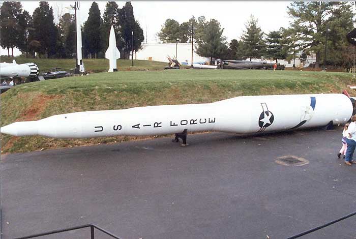
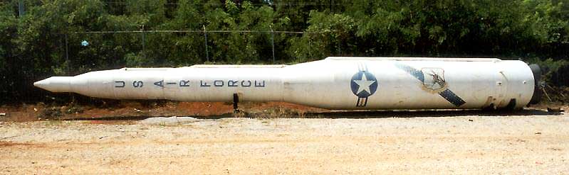
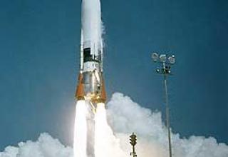
Minuteman" intercontinental ballistic missile (ICBM) belongs to the "second generation" intercontinental ballistic missile (ICBM), which differs from "first generation" intercontinental ballistic missile ("Atlas", "Titan") with the use of RDTT, smaller size and weight, increased reliability and shorter launch preparation time.
Work on the second-generation ICBM began in 1955, when the ballistic missile division of ARDC was established, whose main task at that time was to study the problems associated with the development of an intercontinental ballistic missile with RTR. Based on this research, it became clear that the most important problems in developing such a missile - the development of a new type of solid propellant, the manufacture of engine bodies and guidance and control methods - were quite solvable. At the end of 1957, the development of an ICBM with RCTT began, which was called the "Minuteman". The development program provided for the creation of a simple, relatively cheap rocket, the design of which without changing the basic design could be made various improvements relating to the propulsion system, guidance system and warheads. Progress in miniaturization of nuclear warheads and inertial guidance systems has contributed to a significant reduction in the missile's weight, and the use of RDTT has reduced launch preparation time to a few seconds. Simplification of the entire missile system has greatly reduced manufacturing and operating costs, and has made it easier to disperse into launch bases.
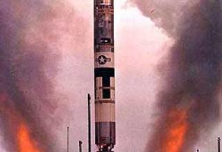
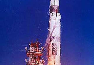
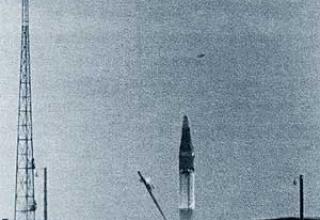
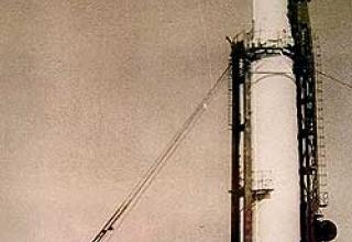
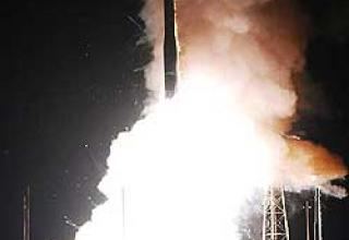
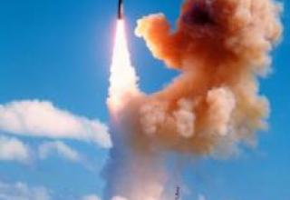
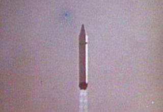
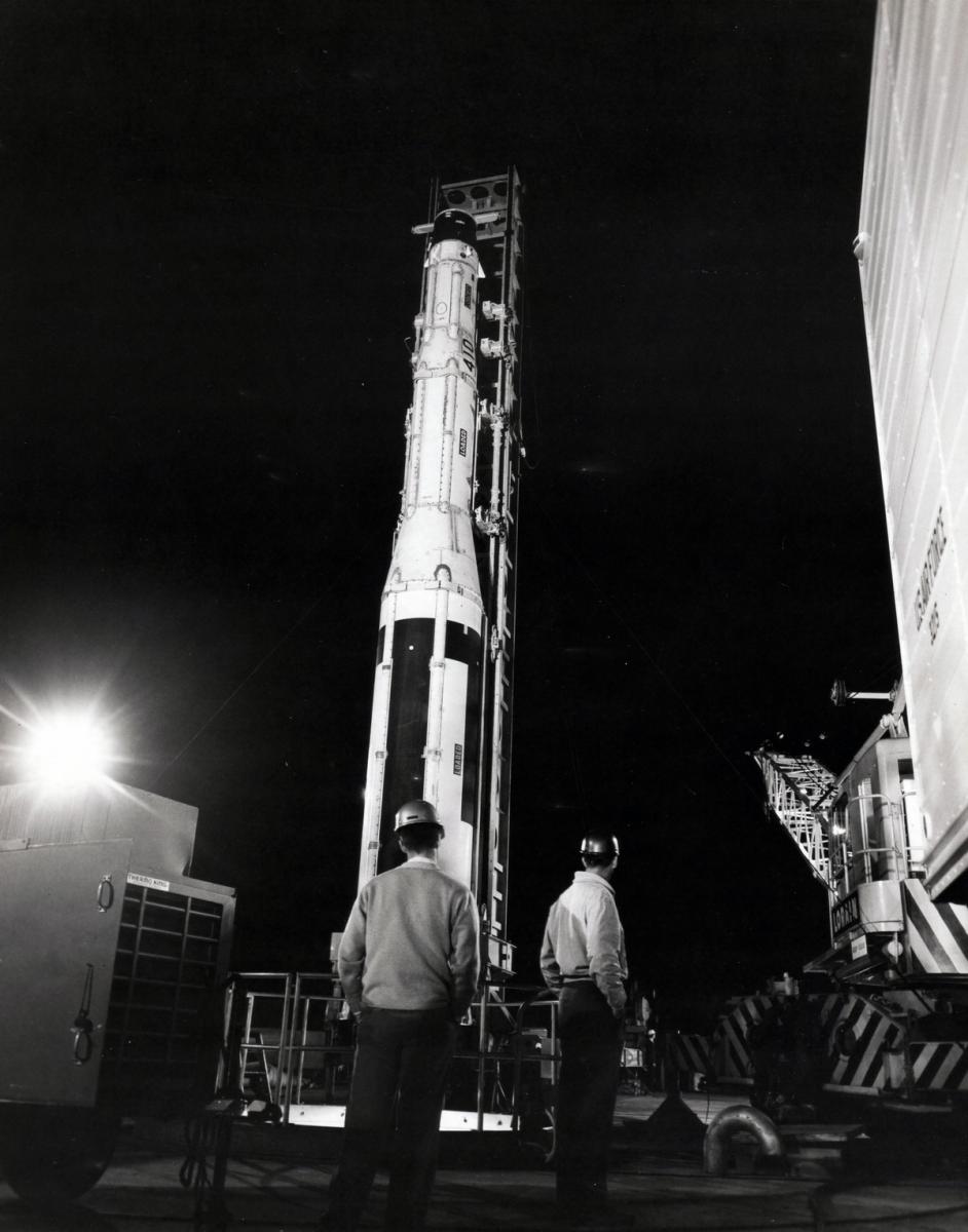
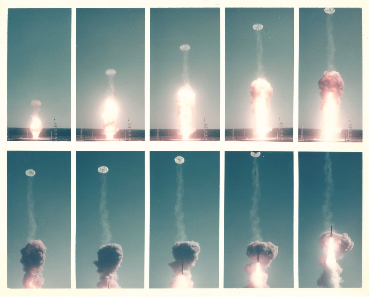
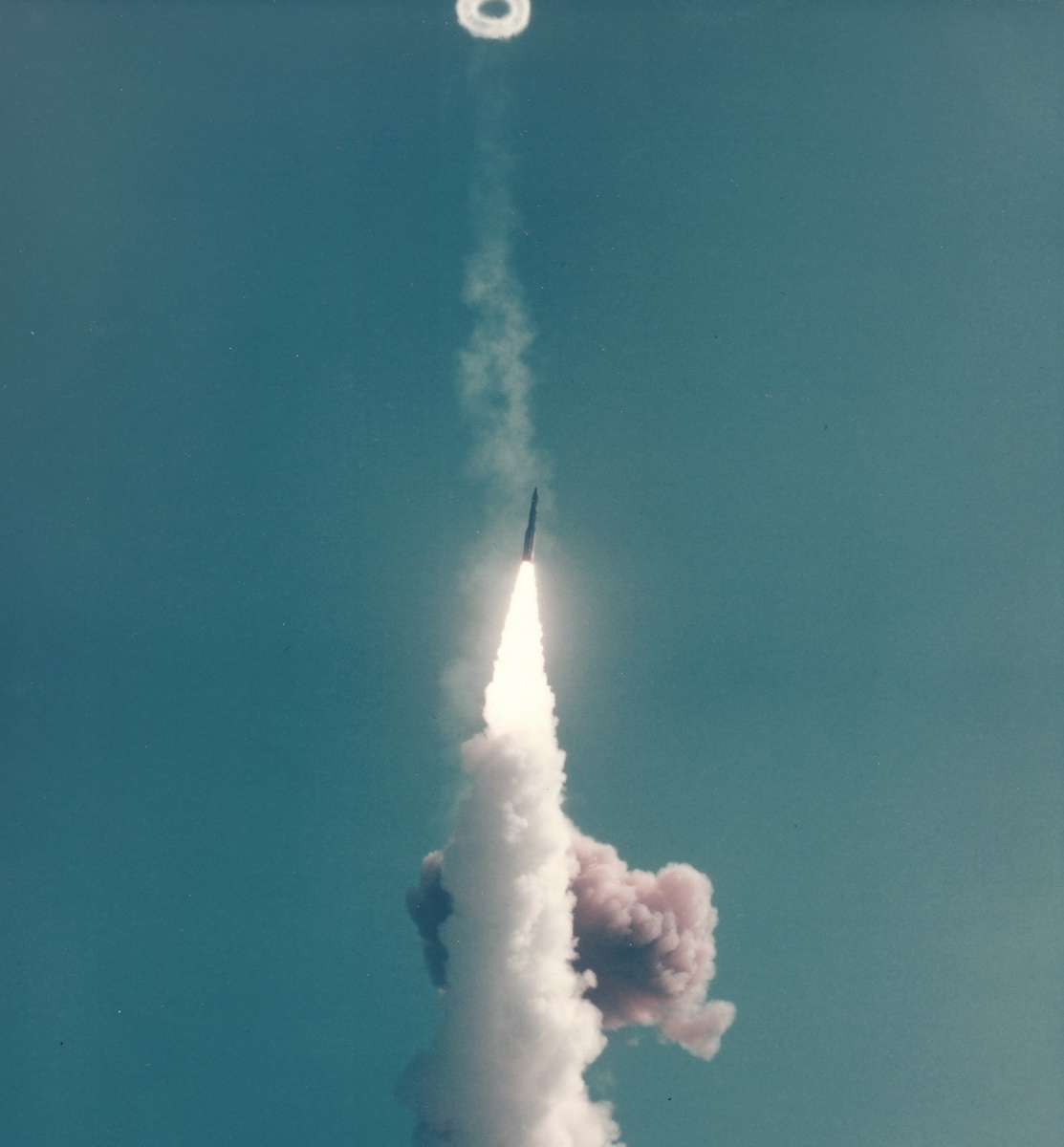
 ICBM launch from LC-31B, Cape Canaveral, 15 February 1962")
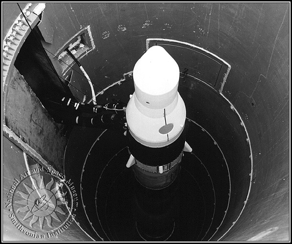
It was planned to create two versions of "Minuteman" - one for launching from underground mines and the other for launching from railway platforms. The first test launch of the experimental rocket "Minuteman" with all equipped stages was made on February 1, 1961 from the ground launch position on the base of Canaveral. The purpose of the launch was to test the engines of all stages and the guidance system, as well as to test the engine activation sequence. The launch was successful, and the rocket flew 7,400 km.
See photos 1, 2 and 3 of the Minuteman-1A (FTM-410) ICBM test launch from the LC-31B site (Cape Canaveral Air Force Base) on 15 February 1962.
The development of the rocket version for launching from railway platforms was stopped in December 1961. The main reasons for the cancellation of the development, which had already spent $100 million, were the high cost of storage and maintenance of missiles on railway platforms, as well as relatively long period of preparation for launch, because the coordinates of the launch site in this case is not known in advance.
The first production rocket "Minuteman" was assembled April 12, 1962, and December 11, 1962 the command of strategic aviation adopted the first two links of missiles, designated LGM-30A / B "Minuteman-1".
In mid-1961, the U.S. Air Force began to study the possibility of modifying the "Minuteman-1" in order to increase the power of the warhead, range and accuracy, as well as to simplify the entire system and improve its reliability. As a result of consistent implementation of this program in 1972, Minuteman-1 missiles were removed from service and replaced by a new modification of Minuteman-3.
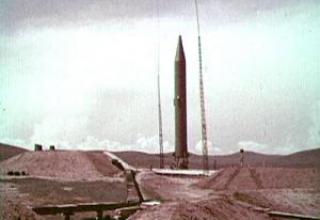
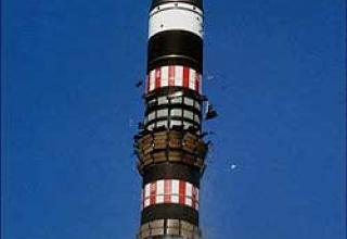
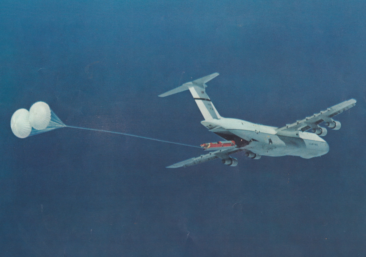
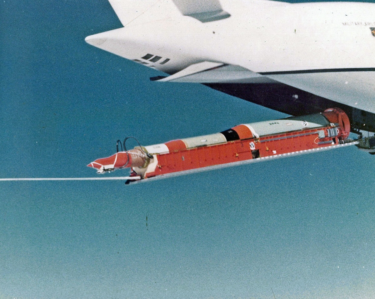
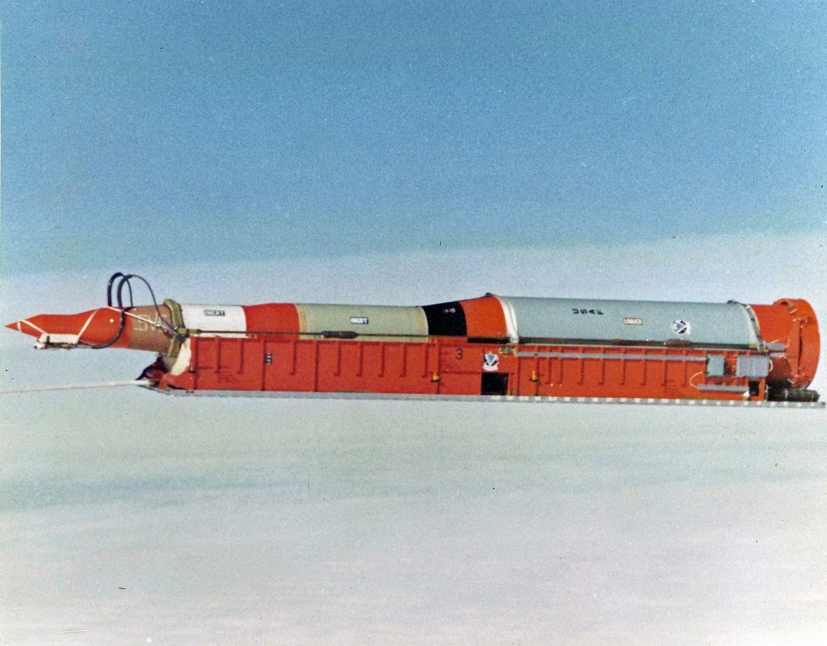
A version of the Minuteman-1 ICBM air launch was under development. October 24, 1974 at the Vandenberg airbase from a heavy military transport aircraft S-5A N 69-0014 from a height of more than 6000m missile mounted on a special cradle, with the help of two parachutes was dropped through the rear cargo ramp of the aircraft. After reaching vertical position in space, the first stage engine was successfully launched (see photo1, photo2, photo3).
Composition:
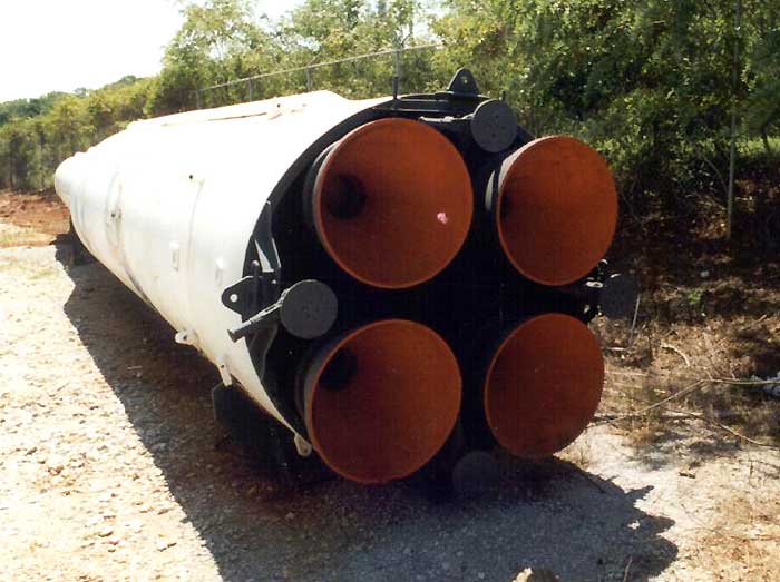
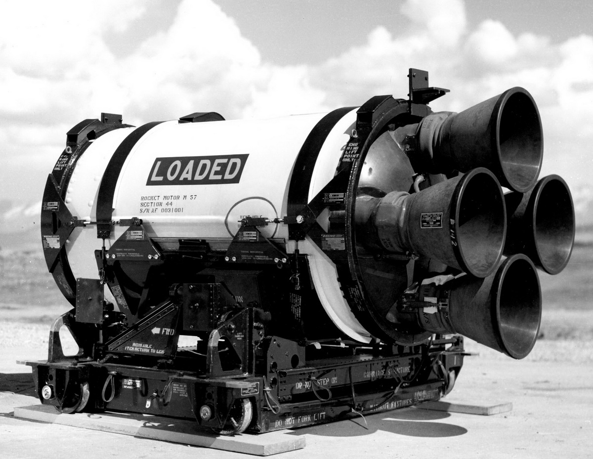
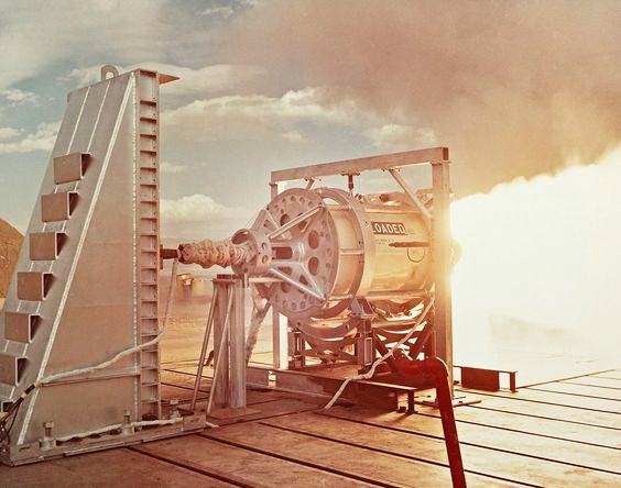
First stage engine:
Developed by Thiokol (TU-122) and working on a blended fuel consisting of polybutadiene acrylic acid, ammonium perchlorate, aluminum powder and epoxy (see manufacturing technology).
The first stage engine has four divergent nozzles. Nozzles 2 and 4 are deflected up and down for pitch control, while nozzles 1 and 3 are deflected one way for pitch control and one way for roll control. Nozzles deflection angle of about 8°.
Nozzle has the shape of a truncated cone with an angle of solution 42 °. The diameter of the critical cross-section of the nozzle is about 0.2 m, the diameter of the output section is about 0.56 m. Nozzles are bolted to flanges mounted on short exhaust pipes protruding from the bottom of the body. Nozzle consists of a steel base and a movable part, connected by an O-ring. The length of the movable part of the nozzle is about 0.63 m. The movable part of the nozzle is made of reinforced phenolic resin with an insulating gasket made of plastic. In the critical section of the nozzle there is a tungsten insert reinforced with six graphite rings, the cross section of which is 3 cm2 at the front of the insert and 6 cm2 at the rear. The inner surface of the nozzle from the critical cross-section to the place with a coefficient of expansion of about four, has a protective graphite coating.
Nozzles are deflected by signals from the guidance system, which are fed to the control unit installed in the central part of the lower bottom floor. The control unit is X-shaped and consists of a self-switching silver-zinc battery, auxiliary power supply, four hydraulic servo-cyllinders and associated electronic equipment. The control unit does not require external power supply. The servocillinders and auxiliary power supply are mounted on a platform that has internal channels that are piped. There are no external piping lines in the system.
The auxiliary power supply consists of a motor, hydraulic pump, stop valve, filters, thermal resistance, 164 oil tank, quick disconnect couplings for filling and draining, and a remote pressure switch. The variable capacity hydraulic pump is connected directly to a 27 V DC compound motor. The weight to output power ratio of this unit is 1 kg/hp. Each of the four hydraulic cylinders of nozzle drives is rigidly attached to the platform. The cylinder piston rod is connected through a floating grain to the fork on the movable part of the nozzle. Each actuator is equipped with a solenoid valve actuated by signals from the servo amplifier of the control unit.
The wiring from the guidance system to the control unit is located on the outside of the motor housing and is covered by a fairing.
Second stage engine:
Designed by Aerojet-General. Due to the relatively small size of the second stage, the motor housing could be made of glass fibre. However, studies have shown that such a solution is inexpedient, because in the three-stage version of the rocket body of the middle stage take heavy loads on the bend and in the manufacture of fiberglass would be too heavy. Therefore, the steel of the same grade as for the first stage was chosen as the construction material (see manufacturing technology).
The second stage engine has four tilting nozzles which are attached to the exhaust pipes at the bottom bottom bottom. Each nozzle has a truncated cone shape and an expansion coefficient of 18. In the critical section of the nozzle is a tungsten insert, held in a graphite gasket about 25 mm thick. The exhaust cone of the nozzle is made of reinforced plastic. Nozzles are deflected using the same hydraulic system as in the first stage. Each nozzle can deflect within 6°.
In the hole, which is located in the center of the upper bottom of the cone, is inserted igniter, which is a small RDTT, fuel which weighs about 900 g and is actually the same composition as the main engine fuel. The igniter goes inside the fuel charge by about 0.5 m and has a safety device that is the same for all three stages.
The engine of the third stage:
Developed by Hercules and operating on a biaxial fuel, the main components of which include ammonium perchlorate with aluminum powder and nitroglycerine-nitrocellulose, which also serve as a binder (see manufacturing technology).
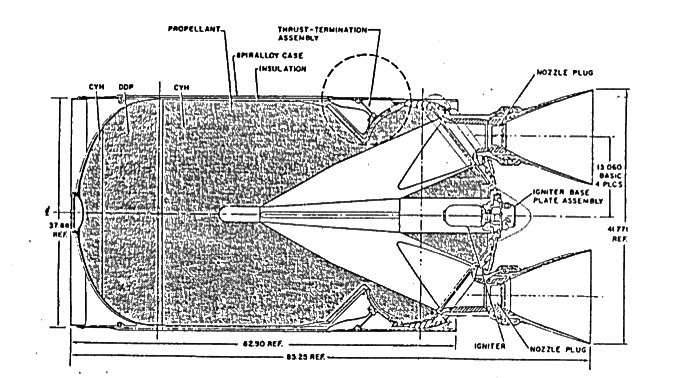
Each nozzle (see diagram), as in the first two stages, consists of a fixed base and a swivel exhaust cone capable of tilting by 4°. The diameter of the critical section of the nozzle is about 0.09 m, the diameter of the output section of about 0.38 m, the coefficient of expansion 18.
The exhaust cone of the nozzle is made by forming under pressure at high temperatures. On the inner wall of the nozzle is an insulating coating, consisting of a layer of quartz fiber reinforced phenolic resin and a layer of resin-impregnated graphite fabric. The graphite fabric has a high thermal conductivity, while the reinforced phenolic resin has a low thermal conductivity. In the critical part of the nozzle is installed tungsten insert on the graphite gasket.
The third stage engine igniter is inserted into the central hole of the lower base. It consists of a small charge of solid fuel, which burns as a result of ignition of powder balls. The ignition unit is equipped with a safety device. The switch of the blasting system for switching off the engine is located on the top skirt of the case. On the outside of the casing, the wiring from the pointing system to the nozzle control unit is located in the fairing.
Connection of all rocket stages is carried out through adapters in the form of truncated cones. Mounting is performed with the help of bolts. All rocket stages are equipped with self-liquidators located under the wiring fairings.
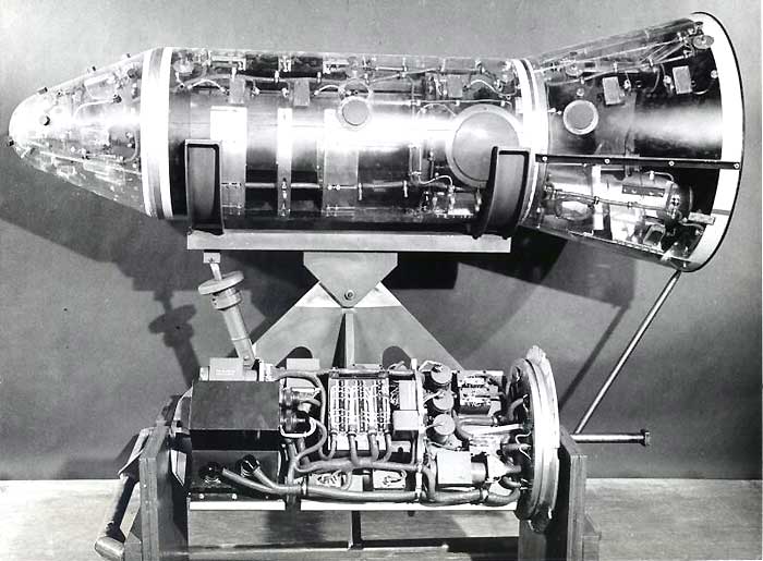
Control system:
The guidance system is inertial, developed by Nord American's "Aztones" department. The main elements of the guidance system are an inertial platform, a miniature D.17 calculator and standard electronic units made on transistors. All guidance system equipment is housed in an airtight container with a diameter of 1.14 m filled with helium, which cools the electronic devices. At the base of the container is a fan and a liquid fuel heat exchanger. From the outside, the container is covered with glass fabric insulation and is placed in an aluminium monocoque casing with a special protective coating before being mounted on a missile. The guidance system unit reportedly weighs about 81.8 kg. The guidance system equipment is powered by silver-zinc batteries.
The inertial platform of the guidance system is mounted on a cardan suspension and can be freely rotated by 90° on the pitch axis, by ± 70° on the roll axis and by ± 20° on the course axis. The platform is stabilised by two two axis free gyroscopes with rotors mounted on gas bearings. One gyroscope serves as a reference for the pitch and roll axes and the other for the course axis (one of the axes of this gyro remains free). Two-axis gyroscopes with gas bearings were chosen because they provide good dynamic stability over a long period of time and can withstand high overloads. Capacitive sensors are used to detect the movement of the gyroscope body relative to the rotor. When storing the missile in a mine, a two-axis level sensor is provided on the platform to correct the position of the pitch and roll gyroscope relative to the local vertical, and the constant alignment of the gyroscope relative to the bearing azimuth is carried out using an optical collimator.
To measure acceleration on each of the three axes, three integrating accelerometers are installed on the inertial platform. Each accelerometer has a pendulum mass floating in liquids to reduce friction. Acceleration on the sensitive axis of any accelerometer shifts the mass, resulting in a signal that is amplified and transmitted to the brake cap driven by the motor, creating eddy currents and torque to return the mass to its original position. There are three two-axis level sensors on the platform which are also used for periodic calibration of accelerometers to monitor the operation of the accelerometers.
In addition to the basic function of calculating the guidance equations, the guidance calculator also performs a number of additional functions related to the assembly of the missile and its verification, both during storage in the mine and in preparation for launch. When assembling the missile, the calculator is used to verify each stage, including testing nozzle control units, stage separation devices and other elements.
After the missile is installed in the launch shaft, the calculator continuously and periodically checks all missile systems during the entire storage period. The quality control of all systems is carried out during the constant check, and the periodic check is more thorough, which determines the accuracy of each element and deviations in the characteristics, and automatically makes the necessary corrections. The difference between the above two types of verification can be seen in the following example. In a continuous check of the control unit, a signal is sent to the amplifier of the control unit to determine that the Servo Drives are deflecting the nozzles in the correct direction, and in a periodic check, the response time of the drives to the signal is also determined.
When preparing the rocket for launch, the calculator performs a prelaunch check and counting time. After the rocket launch, the calculator performs guidance calculations, determines the time of separation of stages, gives a command to shut down the engine of the last stage, determines the moment of separation of the nose cone and raising the combat charge in such a way that it will hit the target.
The calculator solves the basic guidance and control equations, taking into account the aerodynamic characteristics of the missile, and generates control signals based on data on the relative position of the missile from gyroscopes and accelerometers. In this way, the calculator performs the functions of converting the signals of the guidance system into a form suitable for driving controls.
The calculator is a general-purpose counting and solving device with a 27-digit code, in which 24 characters are used for calculations. The memory block of the calculator is a magnetic disk, rotating at a speed of 6000 rpm. The capacity of this unit on missiles of the first modification is 2985 words.
The calculator takes 43 types of data from different equipment and performs two main cycles of calculations: one cycle provides a solution to the guidance equation (where the missile is at the moment in relation to where it should be to hit the target), and the other - the calculation of signals for the control system.
The calculator provides three pairs of output digital signals to introduce corrections to gyroscopes and three output voltages in analog form to drive the control nozzles on pitch, heading and roll. In addition, the calculator provides a signal to drive a paper ribbon puncher or an electric teletype to record test results for verification tests. For experimental launches, the calculator is also used to signal the operation of the telemetry system.
The calculator is designed in such a way that it can be completely reprogrammed by changing the information supplied to the memory unit. To enter data into the memory block of the calculator a programmer placed on a conveyor is used, which is fed to the starting shaft and sends to the memory block the data needed to hit a specific target. All Minuteman missiles in the launch silos are pre-programmed to engage a preselected target.
Since the calculator performs a number of complex functions related to the verification and calibration of the rocket it is necessary to have some devices that check the work of the calculator. The Minuteman system uses a special unit located in the ring room of the upper part of the launch shaft.
Battle unit:
Battle charge - nuclear with TNT equivalent of 1-2 Mgt. Battle charge is placed in the nose cone of burnout type entering the atmosphere. Separation of the nose cone from the third stage at a given speed and location is carried out by reversing the thrust of the third stage engine and blasting the plug in the central hole of the upper bottom. The thrust reverser is synchronized with the release of the nose cone locks.
Characteristics:
| Range of fire, km | 9200 |
| Firing accuracy, km | 0,4 |
| Control System | Inertial with BCVM |
| Number of rocket stages | 3 |
| The length of the rocket: | |
| - complete, m | 16,4 |
| Maximum housing diameter, m | 1,67 |
| Start weight, t | 29700 |
| Control and stabilization bodies: | |
| -I stage | RDTT with 910 kN thrust, 4 rotary nozzles |
| -II stage | RDTT with 210 kN thrust, 4 rotary nozzles |
| -III stage | RDTT with 159 kN thrust, 4 swivel nozzles |
| Stage one: | |
| -length, m | 7,37 |
| -diameter, m | 1,83 |
| -the weight of the harnessed step, t | 22000 |
| TU-122 engine: | |
| -designer | "Thiokol" |
| -type | single-chamber RDTT |
| -height, kgf | 77200 |
| -nozzle number | 4 |
| Fighting unit: | |
| -type | thermonuclear |
| -Charge power, Mt. | 0,65-1,5 |
| -weight, kg | 420 |
Testing:
Of the more than 50,000 launches of Milan missiles (training and combat missiles) carried out in various conditions, 92% ended in a direct hit. The effectiveness of the complex was demonstrated in combat conditions: Iraq since 1980, Syria and Great Britain in 1982, French troops in Lebanon in 1984, Chad in early 1987. With nine PU units of the Chadian land forces hit more than 100 tanks and other vehicles in Libya, using about 250 missiles "Milan-2".
Sources:
- "МБС Боинг "Минитмэн"".(ЛМИ. 1964г).
- "МБС Боинг "Минитмэн" SM-80". (ЛМИ. 1963г).
- http://www.spacecom.af.mil/HQAFSPC/library/facts/lgm30.html
- http://www.fas.org/nuke/guide/usa/icbm/lgm-30_1.htm
- How C-5 Galaxy plane made history in 1974 by being used as a launch pad for 43-TON nuclear missile in radical Cold War test