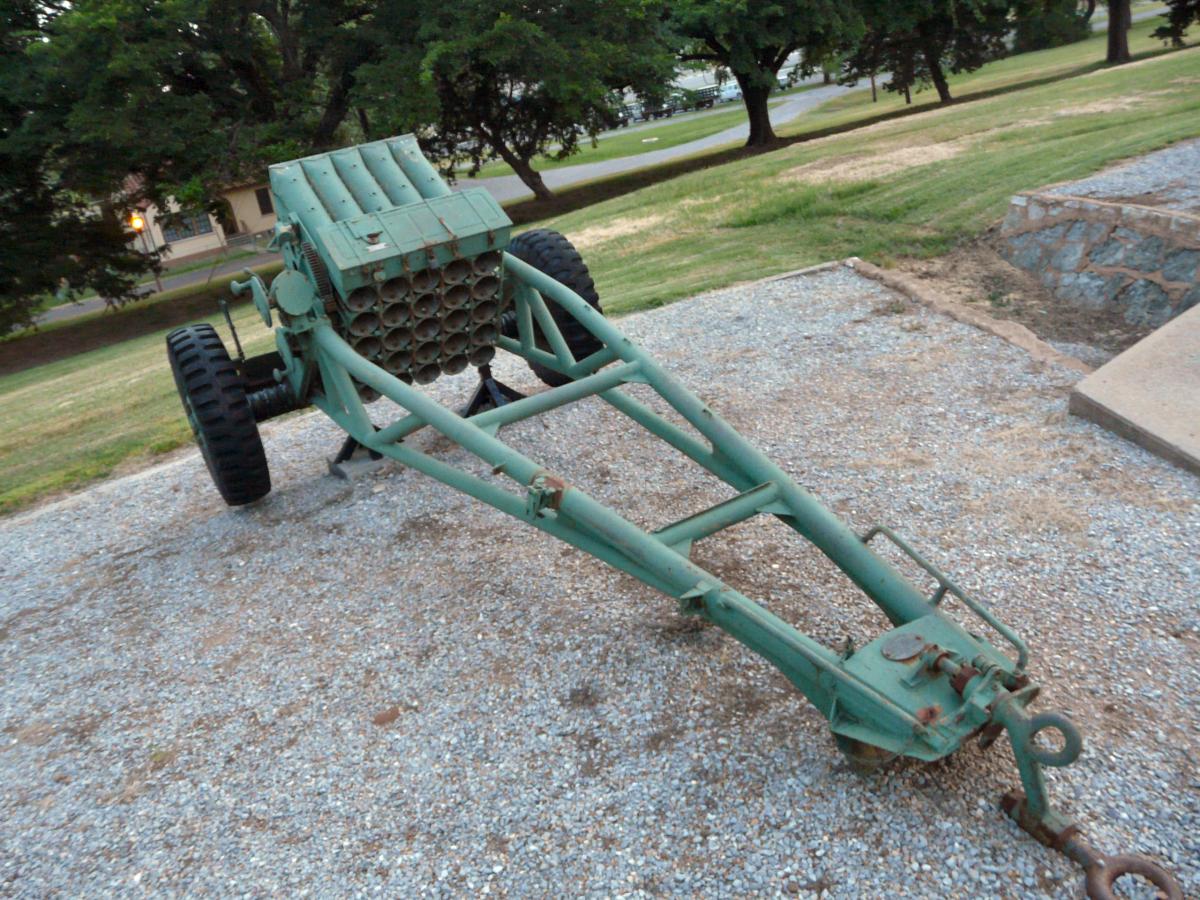
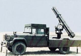
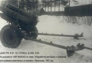
The T123 multiple launch rocket launcher was designed to fire smoke and high-explosive rockets of 114.3 mm caliber at ground targets at a range of up to 5 km.
It was developed in the USA, probably in the late 40s and early 50s. It is currently unarmed. The last time the T123 was used by personnel of the U.S. Marine Corps at Fort Sill in 1979 during tests of new radar equipment.
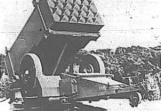
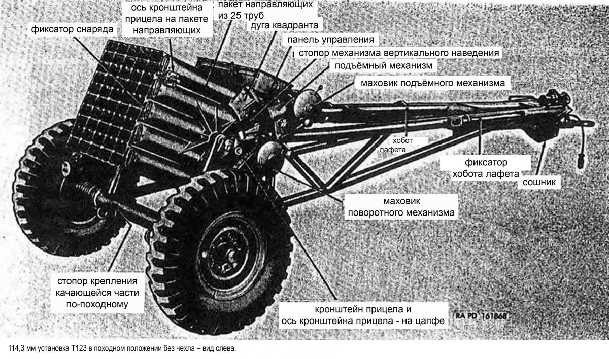
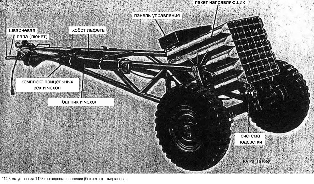
The T123 was mounted on a two-wheeled lever-type carriage with pneumatic tyres and manual parking brakes (see diagram_1, diagram_2, diagram_3). For transportation, an off-road vehicle with a payload capacity of 2.5 t and a 4×4 wheel arrangement was used.
The package of guides T123 consisted of 25 guides. Configuration of the guide package: five rows of five guides in each. Package of guides was balanced on trunnions in bed without mechanical balancing. Handles of vertical and horizontal guidance mechanisms, direct and indirect fire sights were located on the left side of the chassis and were designed to operate with one number of calculations.
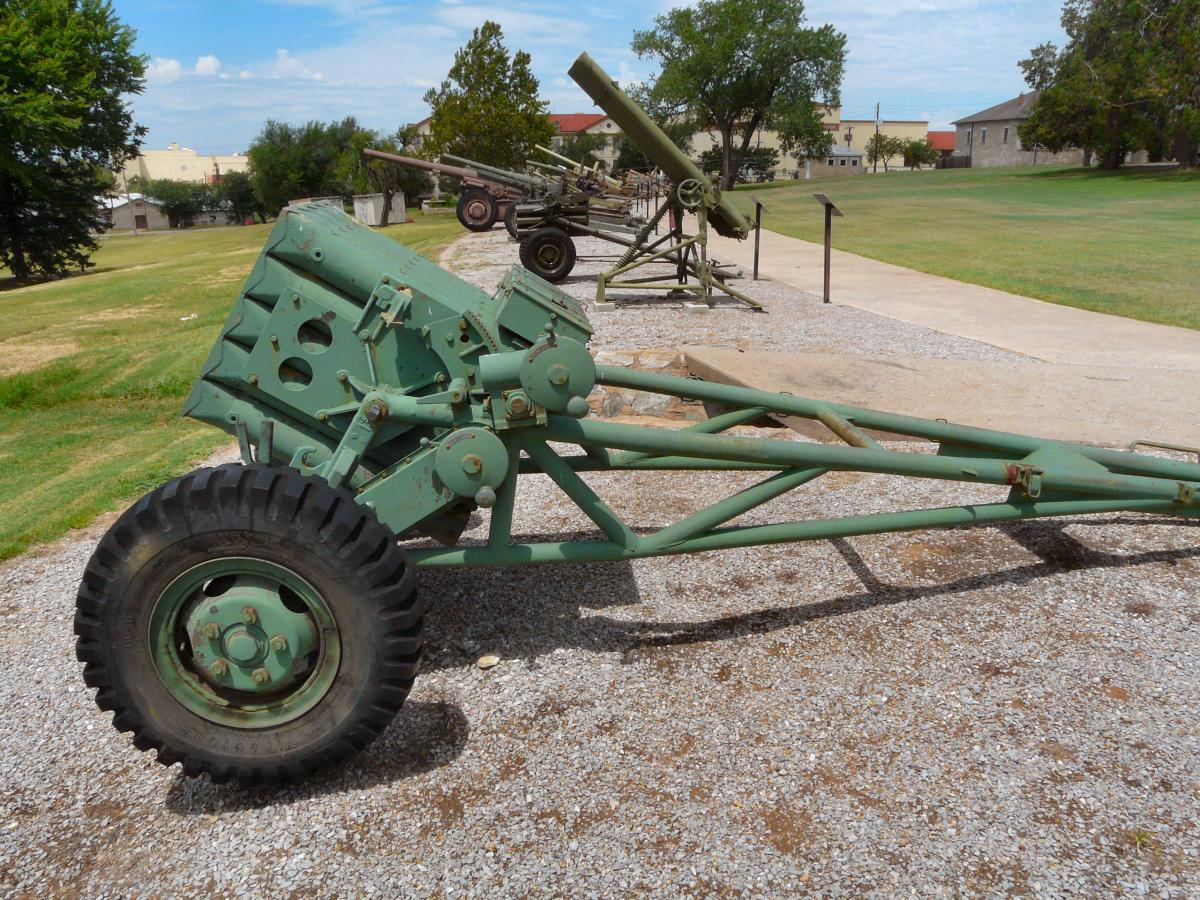
The mechanism of vertical guidance of the worm type, the scale of angles of vertical guidance was placed on a package of guides. Horizontal guidance was provided by rotation of the bed on the chassis axis. Vertical and horizontal guidance stops were used to prevent the guide pack from changing its position during firing.
Unguided rockets (NURS) were loaded into the muzzle-side guides. The ignition of the propellant charge of the rocket unit was provided by an electrical signal. The projectiles were fired one at a time in a set volley sequence. The speed of firing depended only on the speed of the operator with the switch of the firing mechanism. The firing mechanism was located in a remote control panel and included an inductor transmitting a signal through a cable. To avoid lateral movement of the unit during firing, each wheel was locked with a special lock. The locks on the trunk of the carriage and the carriage prevented the carriage from shifting during the firing.
After a fuel charge was ignited, gases, flames and unburned pieces of fuel flowed out of the projectile nozzle block at high speed. When firing, the area around the unit was to be free of personnel and flammable materials. A special plate-shaped gas deflector was placed on the ground under a package of rails and could be used to reduce the dust cloud generated by the firing and to prevent soil erosion. During normal operation, one to three volleys were supposed to be carried out, after which the unit would be towed to a new position.
The unit could be towed in a loaded state. The guide package design used locking pins to secure the NURS in the guides while driving.
Composition:
The missile defense complex includes:
- AEGIS Combat Control System:
- radar AN/SPY-1D(V);
- fire control system Mk 99;
- a ship-wide computer system with 24 AN/UYK-7 and AN/UYK-20 computers;
- display devices like AN/UYK-4 (or AN/UYQ-21);
- 4 indicators of generalized tactical situation;
- hydroacoustic complex;
- radio electronic system on board the helicopter;
- digital LINK-11 communication lines;
- E-2S Hawkeye long-range radar observation and control deck aircrafts, S-3 Viking anti-submarine deck aircrafts and Orion base patrol R-ZS.
- SM-3 missile (RIM-161)
- Vertical Launching Unit (VLU) Mk41;
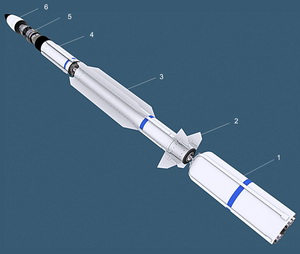
SM-3 has the same mass dimensional characteristics as SM-2 Block IV. The length of both rockets is 6.59 m, the diameter of the accelerator - 533 mm, the diameter of the march stage - 343 mm, mass - 1500 kg. Both missiles are equipped with the same solid-fuel accelerator Mk 72 with a four-nozzle block, acceleration and marching two-mode engines Mk 104, wings of ultra-small elongation and opening block of aerodynamic rudders.
The difference between SM-2 and SM-3 is the installation of a third stage on SM-3, which includes:
- precoaster motor Mk 136,
- inertial guidance section with GPS receiver and data exchange line,
- lightweight dumpable fairing,
- Intercept stage Mk 142, which destroys the target by direct hit.
The Ìk 136 is a solid fuel double-start motor developed by Alliant Techsystems. It is equipped with two solid fuel charges separated by a barrier system, and its design is made of graphite epoxy and carbon-carbon composite materials. The engine run time is 30 seconds. To ensure stabilization and orientation of the third stage of the rocket during the autonomous flight, the engine includes an integrated control system that uses cold gas as a working body.
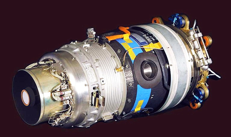
The Mk 142 intercept stage is a self-propelled device with a cryogenic IR-GSN matrix, several processors, a solid fuel propulsion system for maneuvering and orientation (DACS), a power supply and a number of other subsystems on board.
Advertising in the initial stages of the work, Raytheon reported that the range of infrared GHN target detection is more than 300 km, and the use of DACS allows you to deflect the trajectory of its flight at a distance of more than 3-3.2 km.
The creation of such a small-size propulsion system was one of the results of a program launched in the mid-1980s to implement critical missile defense technologies. At that time a number of leading American companies were involved in its implementation on a competitive basis. As a result, by the early 1990s Boeing, the leader in this work, had created the "lightest in the world" (weighing less than 5 kg) propulsion system. It consists of a solid fuel gas generator equipped with several charges, a nozzle block and high-speed (up to 200 Hz) valves, capable of operating at a temperature of 2040 ° C. As noted, the creation of such a design required the use of special heat-resistant materials, in particular, based on rhenium.
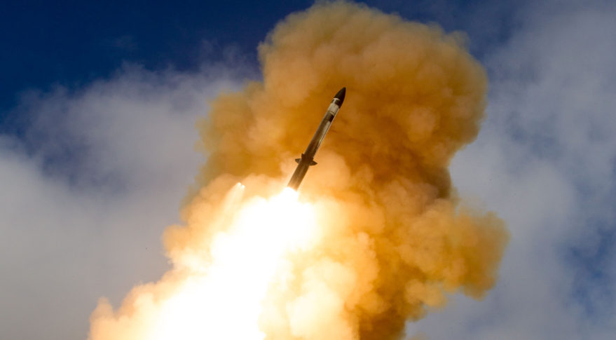
SM-3 is launched from the Mk41 vertical starter, designed for ships equipped with the Aegis system.
Work was carried out to adapt SM-3 rockets for use with ground-based launchers. This version of SM-3 was first proposed by Raytheon in 2003 and was initially developed on a proactive basis. As an option, the developer company proposes integrating the ground-based SM-3 into the THAAD missile defense system.
SM-3 Block IA
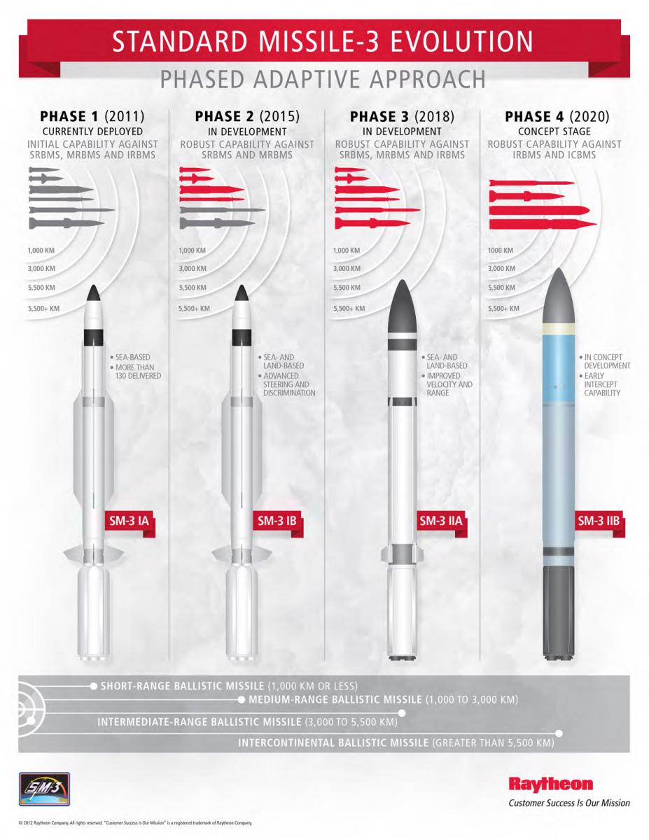
The first variant of SM-3 missile modernization was SM-3 Block IA, which had small improvements in the design of the intercept stage. Flight tests of SM-3 Block IA began on June 22, 2006, during which a number of successful ballistic target intercepts were performed at various points in the trajectory. In addition to the U.S. Navy ships equipped with the Aegis system, a number of these tests involved Japanese, Dutch, and Spanish ships.
The "standard" range and intercept altitude of SM-3 Block IA are reported to be 600 and 160 km, respectively, with a maximum speed of 3-3.5 km/s, which provides the kinetic impact energy of an intercept stage with a target of 125-130 mJ.
In February 2008, after appropriate preparation, this version of the missile was used to destroy the American satellite USA-193 at 247 km altitude.
In February 2013, the SM-3 Block IA interceptor missile launched from the USS Lake Erie cruiser destroyed a target simulating a medium-range ballistic missile. An external target designation from the STSS-D (Space Tracking and Surveillance System-Demonstrators) satellite was used.
SM-3 Block IB
In the development of the next option - SM-3 Block IB - along with American firms, a number of Japanese firms are involved in this work in accordance with the agreement concluded in August 1999 between the governments of the United States and Japan.
The main differences between SM-3 Block IB and Block IA relate to the intercept stage. The SM-3 Block IB missile uses a new 10-nozzle DACS, which is capable of changing the traction value, and a two-color IR-GSN, which increases the size of the target detection area and improves its detection against interference. CCTV is equipped with reflective optics and advanced signal processor, which allows you to intercept targets at ranges greater than previous versions.
SM-3 Block IIА
According to the agreement signed between the US and Japan, radical improvement of SM-3 has been underway since 2004. The development of this option, designated SM-3 Block IIA, began in 2006. The main external difference of the new variant will be that the missile diameter along the entire length will be 533 mm - the maximum allowed by the installation of vertical launch Mk 41 and, therefore, does not require special carrier ships for its location.
The missiles are equipped with a stage of intercept of the increased diameter, improved IR-GSN and more efficient propulsion system maneuvering and orientation TDACS (Throttleable Divert and Attitude Control System) kinetic warhead.
Aerojet's new TDACS (Trottleable Divert and Attitude Control System) solid fuel system with adjustable thrust will provide spatial movement as well as control of roll, yaw and pitch angles during the process of pointing the kinetic warhead at the target in the overatmospheric section of the trajectory. General Dynamics has developed the key technology for a miniature, high-precision throttle control system. The solutions and processes previously developed in the SM-3 Block I versions were widely used in the development.
SM-3 Block IIA will feature a new nose fairing and smaller aerodynamic surfaces.
The use of a large-size acceleration and marching engine as part of SM-3 Block IIA will provide an increase in the final speed of the missile by 45-60%, or up to 4.3-5.6 km/s (so this option is also called High Velocity), and a range of up to 1000 km. In turn, increasing the missile's size will lead to a more than one-and-a-half-fold increase in its launch weight.
The full development cost of SM-3 Block IIA could be $3.1 billion. (The cost of the first missile samples up to $37 million), and it may also include a number of works previously performed by the Agency for Defense under the program to create a miniature intercept stage MKV (Miniature Kinetic Vehicle), which will compete with the currently being developed for the promising variants of SM-3 stage intercept UKV (Unitary Kinetic Vehicle).
The first launch of SM-3 Block IIA is expected in 2014. If the tests are successful, rapid deployment of these missiles will begin in 2015 and full-scale deployment in 2018.
SM-3 Block IIB
In 2011, Lockheed Martin reported that the U.S. Missile Defense Agency awarded it a $43.3 million contract to develop the SM-3 Block IIB missile concept.
The plans for the SM-3 Block IIB further enhance its performance by installing an oversized intercept stage (UKV), which has better target acquisition and detection performance, as well as the ability to maneuver aggressively at the end site (High Divert). The new generation missile will provide early intercept capability for long-range ballistic missiles and will be integrated with the Aegis BMD 5.1 control system.
The SM-3 Block IIB will also utilize remote targeting technology, which will include not only target designation from remote radars and control systems, but also the ability to update target data during flight from other systems, including unmanned aircraft equipped with onboard multispectral targeting systems.
Further plans envisage that by 2020 it will be possible to equip SM-3 Block IIB with several stages of MKV intercept, the mass and size of which will allow to place up to five such vehicles on board. The introduction of such enhancements will make it possible to consider SM-3 Block IIB as an interceptor with ICBMs and their warheads in exoatmospheric flight paths.
Characteristics:
| Trekking position | |
| width, mm | 2019 |
| height, mm | 1464 |
| length, mm | 4547 |
| Distance from kingpin trunk to ground, mm | 800 |
| Distance from wheel center line to kingpin shaft, mm | 4110 |
| Running width (centre to centre of tyres), mm | 1778 |
| Clearance (without coulter stubble), mm | 334 |
| Center of gravity: | |
| horizontal in the middle of the journal, mm | 298,45 |
| vertical below the journal, mm | 215,9 |
| Battle station | |
| width, mm | 2019 |
| height at maximum elevation, mm | 1459 |
| height at an elevation of 0°, mm | 53,9 |
| Total length at an elevation angle of 0°, mm | 4426 |
| Distance from the centre line of the trunnion axle to the ground, mm | 886 |
| Distance from the muzzle cut to the centre of the journal axis line, mm | 498 |
| Guide Package | |
| Caliber of tubular guide (nominal), mm | 115,2 |
| Length of tube guide, mm | 914,4 |
| Distance between centre lines of adjacent guideways, mm | 136,5 |
| Number of tubular guides | 25 |
| Weight data | |
| Weight of unit without equipment, kg | 694 |
| Weight of bed without king-pin bar and king-pin leg, kg | 198 |
| Weight of complete wheel without tire and tire chamber, kg | 55,3 |
| Axle weight, kg | 54,9 |
| Weight of brake drums, brakes and shafts (spindles), kg | 42,6 |
| Lifting weight, kg | 25,4 |
| Weight of guide package without control box, firing mechanism, stud axes and sighting bracket, kg | 240,4 |
| Weight on the left wheel, kg: | |
| at gunpoint | 298,4 |
| hiking | 307,5 |
| Weight on the right wheel, kg: | |
| at gunpoint | 264,9 |
| hiking | 272,2 |
| Weight on coulter (combat position), kg | 119,7 |
| Weight on king-pin leg (hiking position), kg | 103,4 |
| Maximum elevation angle | 75° |
| Angle of declination | 0° |
| Angle of horizontal firing: | |
| to the right of the central axis | 3°34' |
| to the left of the centerline | 3°14' |
| Handwheel speed up to maximum elevation angle | 135 |
| One rotation of the flywheel | 10 thousand |
| Force on the handle of the flywheel, kg | 1,8 |
| Chassis tires | |
| Tire size, inch | 9.00×16 |
| Air pressure in tires | 25-40 psi |
Testing:
It is alleged that two projectiles were launched towards the Israeli capital, the city of Tel Aviv, from Gaza on the evening of 15 November 2012.
The Palestinian terrorist organization Al-Quds Brigades, the militant wing of the Islamic Jihad, claimed responsibility for the shelling. According to their statement, two Fadjr-5 rockets were fired towards Tel Aviv, indicating that the group had hundreds of such rockets.