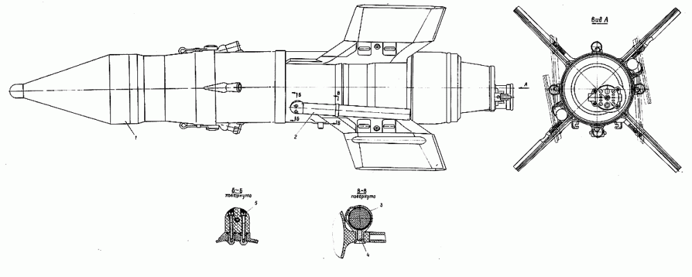
The 9M14P anti-tank guided missile is an upgraded version of the 9M14M projectile, modified to provide semi-automatic firing capability.
The 9M14P projectile is designed to fire at armored targets and firing points from the 9P133 war machine in semi-automatic and manual modes of control. Besides, 9M14P can be used for manual firing from all kinds of launchers, from which 9M14M (9M14) projectiles are fired.
Unlike the 9M14M projectile, the 9M14P projectile is symmetrically placed with two 9X416 tracers instead of a single 9X44 tracer, providing tracking of the heat dissipation factor, which is part of the semi-automatic control equipment on the 9P133 combat vehicle. The 9M14P projectile is fitted with the 9H11OM1 combat unit with increased armor penetration. The 9H11OM combat unit can also be used. Both combat units can be equipped with both 9E236 and 9E212 fuses.
The distinctive feature of the 9M14P1 is the absence of an electric circuit running through the projectile body and the combat unit to the bottom of the explosive device in comparison with the 9M14P. Therefore, the projectile is equipped with only 9M110M2 combat unit, which uses only 9E236 inertial detonation device. The projectile 9M14P1 may not be equipped with combat units 9H110M and 9H110M1.
Basic principles of projectile control
When the 9M14P projectile is used in systems with semi-automatic control, the operator's functions during the pointing process are reduced to holding the mark of the sight on the target. The projectile is brought to the line of sight and held on the line of sight until it is encountered with the target.
Deviations of the projectile from the line of sight in two planes (rate and pitch) are perceived by the photoreceiver of the heat dissipation unit and converted into electrical signals, which after amplification and conversion are fed to the counting and solving unit (PSC) of the control equipment.
In the PSA, these signals, proportional to the angular deviation of the projectile, are converted into signals of linear deviations from the guidance line at the rate and pitch and are fed into the control signal formation unit of the automation unit. The control signal from the automatics unit is transmitted to the onboard projectile control system via wire communication line. Development of commands by 9M14P is similar to their development by 9M14M projectile, as the onboard control systems of these projectiles do not differ from each other. The principles of manual control of 9M14P are similar to those of 9M14M.
The following components have been modified in 9M14P as compared to 9MI4M:
- a combat unit with an explosive device;
- wing compartment;
- tracker;
- resistance block.
The rest of the projectile nodes remain unchanged.
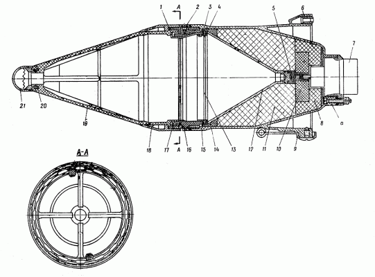
Battle unit with an explosive device.
1 contact; 2 screw; 3 ring; 4 gasket; 5 spring; 6 block; 7 bottom part of the explosive device; 8 draughts; 9 lever; 10 lens; 11 draughts; 12 complete funnel; 13 spring gasket; 14 insulator; 15 body; 16 body; 17 piezo; 18 nut; 19 cap; 20 tip; 21 cap.
The main difference between the 9H110M1 combat unit and the 9H110M military unit is that it uses the new explosive substance (BB) "OKFOL" and the more advanced bottom part of the 9E236 explosive device.
The casing 15 of the 9H110M1 combat unit differs from the casing of the 9H110M combat unit in the absence of wires for the supply of the electric impulse to the electric fuses of the fuse device, in connection with which the ledges for fastening the wires were removed. When completing the 9H110M1 combat unit, the bottom part of the 9E212 fuse device is placed from the 9H110M combat unit with the wires.
The cumulative charge of the 9H110M1 combat unit is the same in its device and dimensions as that of the 9H110M combat unit. The only difference is that the 8 to 11 draughts are made of "OKFOL" Air Force and the funnel 12 has been slightly modified.
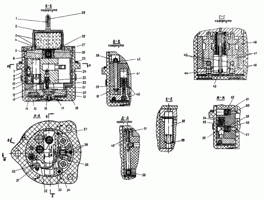
The 9E236 explosive device is a piezoelectric, instantaneous reactive, safety type, with self-contained detonation and self-liquidation. Introduction of the explosive device occurs on distance of 70-200 m from starting installation. the explosive device 9Э236 consists of two basic parts: the head, borrowed from the explosive device 9Э212, and the bottom, connected among themselves switching chains similar to chains of a fighting part 9Н11ОМ.
1-cap; 2-cap; 3-blasting substance; 4-caps; 5-caps; 6-cap; 7-spark electrodetonator; 8-cap; 9-engine spring; 10-branch; 11 sleeve; 12-tube; 13,40,54,58,61 - pyrotechnic composition; 14 - gasket; 15 - gasket; 16 - nut; 17 - contact; 18 - body; 19 - contact; 20 - ring; 21 - spring; 22 - caps; 23 - engine; 24 - bushing; 25 - gasket; 26-cup; 27-nut; 28-hole; 29-contact; 30-axis; 31,43-ball; 32-big lever; 33-axis; 34-small lever; 35-pin; 36-axis; 37-spindle; 38-nut; 39-contact; 41-piece detonator; 42-washer; 44-spring; 45-sleeve; 46-screw; 47-balance; 48 sleeves; 49-springs; 50-caps-igniter; 51-spring; 52-needle; 53-spring; 55-sleeve; 56-plug; 57,60-sleeve; 59,62-sleeve.
The bottom part of the 9E236 detonator consists of the following main components and mechanisms:
- of the safety-trigger mechanism;
- the engine components;
- ignition mechanism;
- long-range trigger units;
- self-liquidation units;
- anti-adhesive device;
- detonating device;
- case and auxiliary parts.
The safety-trigger mechanism is designed to ensure safety of the explosive device E.E. The safety-trigger mechanism consists of a sleeve assembly 48 with zigzag grooves, two balances 47 with pins 35 pressed into them, two screws 46, two axes 36, sleeve 45, spring 44 and two balls 43.
The propeller assembly shall serve to remove the electrodetonator from the detonation circuit of the explosive device in service, to transfer it to the combat position in flight and to switch the electric circuits after the bottom part of the explosive device has been started.
The assembly of the propeller consists of propeller 23 with a spark electrodetonator (EED) 7 pressed by a bushing 11; cap 8 with a spring 9; cap 22 with a spring 21; two stoppers 57 and 60 and two pyrotechnic compositions (fuses) 58 and 61 placed in all bushes 59 and 62.
The ignition mechanism serves for ignition of the pyrotechnic composition of the long-range activation and self-liquidation units. The ignition mechanism consists of a trigger device and an annular mechanism. The trigger device holds the trigger mechanism in service and consists of a large 32 and small 34 levers with axes 30 ya 33 and a ball 31. The trigger mechanism consists of a sting 49 with spring 51 and a bushing with a capsule-ignition 50.
The long-range firing unit serves to ensure the firing of the detonator at a given distance oi the launcher and consists of a bushing 55 with the pyrotechnic composition pressed into it 54.
The self-liquidation unit provides for the elimination of the projectile warhead in the event of missed target and failure of the detonator on the ground. The self-destruct unit consists of a 20 ring with a pressed pyrotechnic composition of 13 and 40, a detonator capsule 41, metal 15 and cloth J4 gaskets.
The anti-adhesive device is used to ensure non-initiation of the engine in case of accidental triggering of the ignition mechanism or painting of the composition in bushes 59 and 62 in service, in case of jamming and missing from the rails or gluing of the projectile after a period of time not exceeding 0.2 - 0.3 sec from the moment of leaving the rails. The anti-skidding device consists of diving 52 and spring 53.
The detonating device is used to detonate the projectile when encountered with an obstacle and consists of a transfer charge and a detonator. The transfer charge consists of cup 26, cap 5 with BB 3 pressed into it. The transfer charge is placed in bushing 28, which is the armature of the cap 6. The detonator consists of a cap 2 with pressed into it BB 3 and a cap 4.
Case and auxiliary parts. All parts and assemblies are connected to bushing 24 using studs 37 and .nuts 38, placed in housing 18 and pressed with nut 27. The stud bolts 37 are simultaneously clamps for cover 6 and ring 20. Plug 56 is used to seal the gases. Pins 17, 19 and nut 16 are used to provide a short-circuit circuit for the head part in service in the assembled combat unit, as well as to connect the spark electrodetonator to the chain of the head part after the bottom part of the explosive device is started up. The tightness of the bottom part is provided by the use of sealant in the screw joints of nut 27 with housing 18 and cap 1 with nut 27.
Action of the combat unit and the detonating device.
When fired under the action of linear accelerations of the shell, shell casings 48, compressing spring 44, settles down. The subsidence of the cartridge case is slowed down (within 0.1-0.2 seconds) due to the braking of the cartridge case with the balance 47, which it is supposed to drive in oscillating motion by engaging the pins 35 with the zigzag grooves of the cartridge case. At the same time it is lowered to the extreme lower position by diving 52, compressing spring 53.
After lowering the cartridge case, the small lever 34 is released, which turns around axis 33 from the pressure of large lever 32, releases the last lever. The large lever 32, turning around axis 30, releases ball 31. The latter, in turn, releases the sting 49, and it, under the action of spring 51, moves down, piercing the ignition cap 50. The force of fire from the igniter capsule ignites the pyrotechnic compositions in the ring 20 knots of self-liquidation, in the bushing 55 knots of long-range and in the bushing 59 knots of the engine.
After combustion of the composition in the bushing 59 engine 23 under the action of a compressed spring 9 engine squeezes out with its bevel stop 57 and moves to the stop with another bevel in the stop 60. This movement takes place at the starting point of the projectile trajectory, when dived 52 continues to stay in the extreme low position. When slider 23 moves all the way to the stop 60, the divers are blocked by slider 52.
As a result, after the end of the linear accelerations 52 could not go up and keep the slider 23 from further movement. After burning out the pyrotechnic composition 54 in bushing 55 ignites the pyrotechnic composition 61 in bushing 62, on burning out of which the engine 23 squeezes out the lock 60 under the influence of a spring 9 of the engine moves to the stop in the bushing 24. At movement of slider 23 there is an opening of a chain of short circuit of a head part (the cap 22 falls off from contact 19 and becomes on a ring 20, isolated from contact 19). At the same time, the spark electrodetonator 7 is connected to the chain of the head part (spark electrodetonator cap 7 jumps from contact 10 and stops at contact 19). Spark detonator 7 becomes against the transfer charge in bushing 28. The bottom part of the detonator is charged.
When an obstacle is encountered at the poles of the head unit, an electrical charge is generated which triggers a spark electrode detonator 7. Electrodetonator 7 triggers a transfer charge in bushing 28, which triggers a detonator in cap 2. If the projectile does not hit an armoured target and the detonator fails over the ground, the bottom part is self-liquidated in this sequence. After burning the pyrotechnic composition 13 in ring 20, the force of fire triggers the cap-detonator 41, the explosion of which in turn causes the detonation of spark electrodetonator 7, and the last - the detonation of the transfer charge and detonator.
Tactical and technical data.
| Maximum range of controlled flight, m | 3000 |
| Minimal aiming range | 400 |
| Average marching speed, m/s | 120 |
| Caliber, mm | 125 |
| Length, mm | 860 |
| Transverse dimensions of the projectile with folded wings, mm | 185 X 185 |
| Start weight, | 11.4 |
| The dimensions of the capping 9YA618 (with one shell), mm: - length - altitude - width |
1051 340 350 |
Смотрите электронный вариант издания: Изделие 9С446. Техническое описание. Часть I. БЛ1.335.005 ТО/. - М.: Воениздат, 1980. - 120 С. (для изделия 9П133 и снарядов 9М14П1 (9М14П), 9М14). https://yadi.sk/d/wai0vgd6Zbjr2


