
The launch unit is a self-propelled launcher that provides a set of works for preparing and conducting rocket launches. It is designed:
- to transport missiles;
- to transfer a missile from a camping position to a combat position;
- to test the 8K14 missile using test and launch equipment mounted on the launch vehicle;
- to refuel the missile with launching fuel and compressed air;
- to point the missile at its target;
- for rocket launch production;
- to move the missile from a combat to a camping position in the event of a failed launch.
The starter unit (see layout diagram) is mounted on MAZ-543 wheel chassis and consists of the following components and systems:
- retrofitted chassis;
- an arrow;
- table;
- deckhouse;
- hydraulic system;
- electrical equipment;
- pre-start service system (PS);
- MIS-O kit
- pointing set 8Sh18.
MAZ-543 chassis is the base on which all components of the starter unit are mounted. The rocket is fixed to the boom. The boom is hinged to the rear beam and can be raised to an upright position. In the hiking position, the boom is supported at the front by the boom support that is mounted on the vehicle frame at the second axle. The boom is connected (locked) to the boom support using a locking mechanism. The table is hinged to the rear beam on the same axles as the boom. When the table is lowered, it is held in place by the stops. The rear beam, which is the base for mounting the boom, table, supports and table stops, is welded to the tail of the car frame. In the middle part of the vehicle frame, the deckhouse is mounted and attached to the spars, which contains the equipment necessary for the operation of the SA.
The lifting and lowering of the boom and table as well as their locking and unlocking are performed by hydraulic drive. Table supports, CA supports, boom grips, table swivel mechanism and table supports are electrically driven. All CA mechanisms are electrically controlled from the control panel and the table control panel.
To increase the reliability of CA operation in case of electric equipment failure, all mechanisms with electric drive have manual redundancy; control of the hydraulic system in this case is carried out directly from the control panel of hydraulic equipment. Ladders are installed on the right and left sides for the maintenance of the CA. The SA can be moved either by its own means or transported by rail, water and air. The CA must be shrouded in a hiking position and during transport.
The equipment of the car chassis consists in installation on it: a rear beam, a rack, brackets, fenders, two ladders, a catcher, boards, units of fastening of accessories and tools, as well as elements of electrical equipment, hydraulic system and STR.
A tow rope with a block is fixed on the bumper of MAZ-543 vehicle. On the left fence of the vehicle fuel tanks there are brackets with belts for fixing the thermo cover. On the right fence there are brackets for fixing the tapered tray and brackets for the spare chamber. A catcher is installed between the left and right fencing of the MAZ-543 vehicle fuel tanks. The catcher is designed to catch the Sh39 plug when the boom with the rocket is lifted. The catching chain is attached to the bottom of the tray. A rope is attached to the upper ring of the chain by a carabiner, which limits the fall of the plug connector Ш39 forward. When servicing the missile, the Š39 plug connector is disconnected from the plug box on the deckhouse roof and docked to the missile; in doing so, the chain of the catcher is connected to the ring of the plug connector. Between the catcher and the fence of the fuel tanks of the car on the right and left side are installed shields designed to protect the elements of the hydromechanical transmission of the car while servicing the launch unit and the rocket.
In the middle part of the chassis, on the spars, bolts are fixed stand, which is used to attach the boom support on it. In the rear fenders in the tail end there are built-in boxes with covers. In the left drawer there is a table control panel, in the right drawer - ZIP. The right front fender has two posts connected to each other by a spacer. The props are used to attach scrap, shovels and saws. On the right and left front wings are fixed ladders for servicing the unit. In a hiking position, the ladders are locked with pins. Between the wheelhouse and the fence of the vehicle's fuel tanks on the right and left along the starter unit are shields to protect the unit from dirt. There is a socket for attaching 3 cans on the rear beam. One can holds the oil reserve for the starter unit's hydraulic system, the other two are for the car's oil. Two table support flanges are welded to the side walls of the rear beam on the left and right. A bracket is welded to the rear beam, on which an angle piece is screwed down. The arrow welded to the cheek of the rear beam, on a scale screwed to the boom, shows the angle of lift of the boom. In addition, brackets are welded to the jaws of the rear beam on the outside to secure the control panel and the ZIP box and the support bracket.
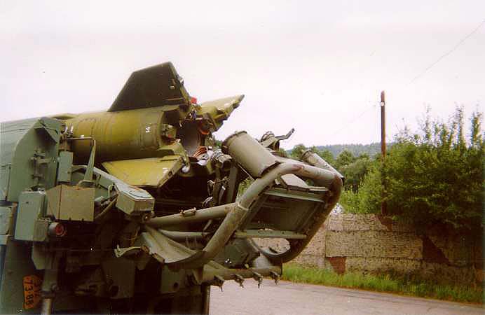
The boom is designed for fixing, lifting to the vertical position of the missile. The supports of the missile are the boom's spools. The missile is held against vertical and longitudinal movements by the boom grips and fittings. The boom consists of two longitudinal beams, two cross beams, a jack beam, two hangers, a balancer, two fittings, assembled fittings, a hook-up, two ladders, brackets, sheets, brackets and panels. In addition, the boom is equipped with electrical and hydraulic components.
The balancer provides support for the front of the missile. The balancer consists of two longitudinal beams, fence, two trays, brackets and two grips. When working with the 3H8 head end, the upper belt is fixed in the front brackets and the tapered belt is bolted to it. When working with other head units, the belt is fixed in middle brackets, and the conical belt is removed and fixed to the right fence of fuel tanks of MAZ-543 vehicle. Fence pipes are welded in the front part of the beams. The fence is sliding and serves to protect the missile head part. The position of the fence is fixed with a finger.
Boom support is a support for the boom in a hiking position and has a device for stopping the boom.
The table is intended for installation on it of a rocket at start-up, for verticalization of a rocket and its pointing on a target; the metal structure of a table is used also for fastening of replaceable cables, hoses of STR in a campaign position and on a starting position and other auxiliary equipment. The table is hinged by means of axles attached to the cheeks of the rear beam. In the hiking position the table is attached to the boom with hydraulic stop jacks mounted at the rear ends of the boom. The table can be raised or lowered either by the table hydraulic jack or (together with the boom) by the boom hydraulic jack. The table consists of the following main components: frame, reflector, bottom part, swivel part and swivel mechanism The table stops are designed to hold the table in position. The supports are designed to support the rear part of the starter unit. The supports are attached to the right and left sides of the starter unit to the brackets of the rear beam.
The rack is a cabin and is designed to accommodate power sources, control equipment and crew of the starting unit, the main pump of the hydraulic system, sets of 8Sh18 instruments, boxes of ZIP-O kit and other equipment. The cutter is installed on the spars of the vehicle. It consists of a frame with lining, doors, windows and hatches. The inner volume of the cabin is divided by partitions and protruding parts into separate compartments. In the wheelhouse there are seats for starter rooms. The interior volume of the deckhouse is divided by a ledge formed by a recess for the car chassis into two compartments: right and left. In the right compartment there is a compartment for a diesel unit. A hole has been drilled on the outer (right) wall of the compartment, closed with a plug, in which the shaft for the drive of the diesel heater is inserted. There is a battery compartment on the left side of the cabin. Above the battery compartment there is a recess for the installation of the Sh90 and Sh91 connectors for external power supply. There is one door each on the side walls of the right and left battery compartments. The doors have one window each, equipped with a light-masking curtain fastened with clasps. The hatches are designed to facilitate maintenance of the cabin equipment, as well as for cabin ventilation and diesel unit cooling. The cabin is hermetically sealed and (together with the HLF) protects the personnel in it when the starter unit passes areas contaminated with radioactive dust, chemical and bacteriological weapons. The cabin has 3 seats: one in the right and two in the left compartments. The backrests of the seats can be folded down for easy access to the cabin equipment.
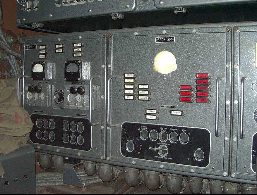
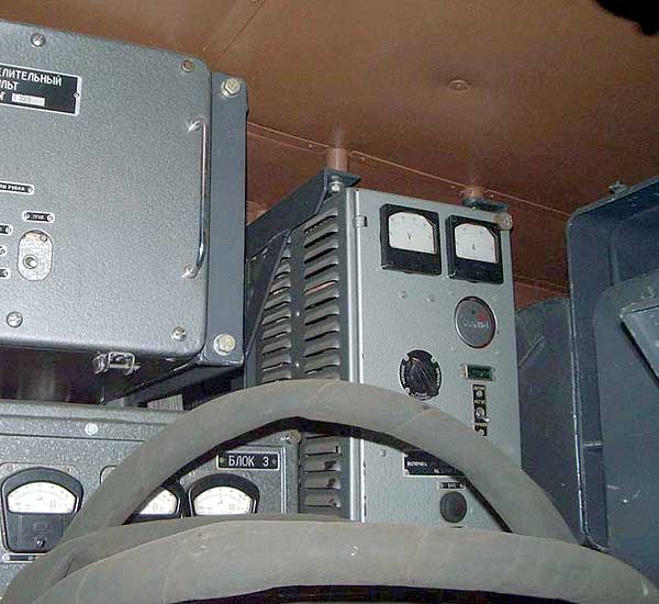
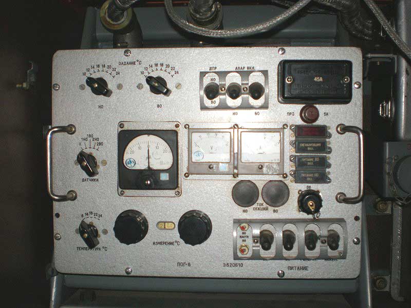
In the left compartment there are 2B12M (2B12M-1) post, switchboard RP, control panel of diesel generator control unit ShchUG, 2B26 IPAPR-3, 4A11-E2. 1 Sb-1 (4A11-E2-II), 9B151, POG-6 (POG-5, POG-5M), indicator unit P61502-1M (P61502-1), storage batteries, relay regulator P10TKM, two filters F-10. The units equipped with 2V12M-1 console have a code blocking device (CBU) - console 9V362M1.
In the right compartment are located: diesel-electric unit, PA battery panel, additional resistance and resistance unit. Outside on the front wall are installed: a socket for connecting the device 8Sh18 and a socket Sh72 to connect the remote control 9V344. A hydraulic pump is installed in the front part of the deckhouse above the ledge. Boxes of ZIP-O SA kit are fixed on brackets and brackets on the back wall of the deckhouse. There are lighting, heating, ventilation and telephone elements in the deckhouse.
There are 2 carbon dioxide fire extinguishers ОU-2 in the cabin. In the left compartment on the floor under the folding seat there is a tank with neutralizing fluid. There are 3 tanks for drinking water in the cabin: one in the right compartment and two others in the left one. In the left compartment, there is a thermometer on the side wall near the door to measure the temperature in the wheelhouse. Near the thermometer, there is a traction gauge for measuring overpressure in the wheelhouse. In the left compartment, on an inclined plane, there is a pocket in the left compartment, which is intended for temporary placement of operational documentation during operation of the start compartment. There is a place for small arms and a box for ammunition in the deckhouse. If necessary, case 9Y51 can be installed on the cistern attachment bracket located in the left compartment of the deckhouse. Case 9Я51 is designed to protect the product KZ-6 (case 9Я52- to protect the product 57-SV-392) from external influences during operation and storage.
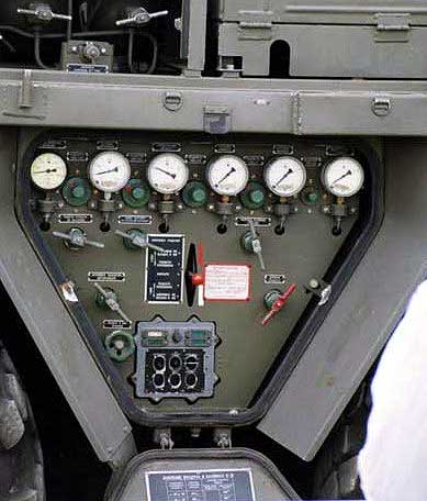
Prelaunch Service System (PS) is designed to prepare fuel and pneumatic systems of the rocket for launch and ensure their performance during the launch of the rocket. In this case, the START provides for the following operations:
- checking the pressure in the pneumatic block and refueling the rocket cylinders with compressed air from the launch unit cylinders;
- filling the pneumatic block of the 3H8 head unit with compressed air;
- rocket refueling with starting fuel;
- use of ampoule batteries;
- refueling of cylinders for starting a car engine from the compressor UKS-400 and from the starting unit cylinders of the START.
It also provides for the following operations with the missile in case of launch cancellation or in case of RIA (emergency engine shutdown) of the missile:
- draining the launch fuel dosage from the rocket;
- releasing air pressure from the rocket's air block.
The STR includes: power units, control equipment, auxiliary equipment, accessories and STR equipment.
Electrical equipment of the starter unit is designed to ensure the operability of components and mechanisms of the starter unit, having electric drives or electromagnetic control, equipment IPESU, as well as to provide the necessary conditions for the work of the start compartment (lighting, heating, ventilation, alarm, radio and telephone communications. Electrical equipment of the starting unit is supplied with voltage 27 (+2 -3) VDC on two-wire circuit.
Electrical equipment of the starter unit includes:
- energy sources:
- diesel electric unit APD-8-P/28-2;
- generator GDL-10;
- accumulators of the unit (two accumulators 12-ST-70);
- external power supply source of the starter unit electric equipment can be a benzoelectric unit of 8H01M type (or any three-phase AC network of industrial frequency voltage 380/220V) together with an electric converter unit 8H026. The external power supply source is connected to the starter unit through plug connectors Ñh90, Ñh91 located on the left side of the deckhouse.
- main equipment:
- switchboard located in the left compartment of the deckhouse on the ceiling and designed to switch the power supply sources of the starter unit in order to provide power to the control consumers of general electrical equipment;
- control panel, designed to control the hydraulic system, electromechanisms of supports, stops, grippers and lighting of the starter unit;
- a table control panel designed to control the electromechanisms of the table supports and the swivel mechanism (installed in a box built into the left rear wing);
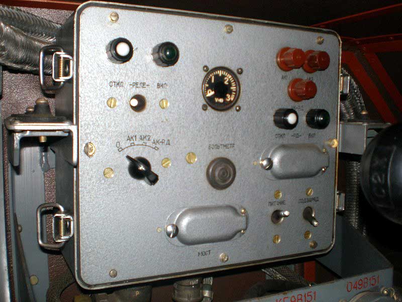
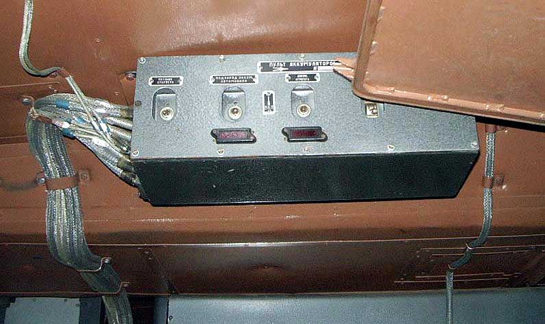
- battery panel designed to prepare the power supply circuit of the starter of diesel-electric unit APD-8, turn on and off the batteries of the unit, turn on and off the fan of the right cabin compartment (located in the right cabin compartment);
- test and start-up electrical equipment.
- actuating elements:
- electromechanisms MWT-300;
- relay regulator R10TKM (R10TKM-1C);
- microswitches;
- verticalization sensor JM-9B.
- auxiliary equipment:
- electromagnetic clutch ETM-093AbP;
- additional resistance;
- resistance block;
- filters F-10;
- ventilation means;
- means of heating;
- means of illumination;
- means of alarm system.
- switchgear and cable network
- communication equipment:
The test and launch electrical equipment is designed for pre-launch checks and launch of the rocket. The electrical test and launch equipment includes:
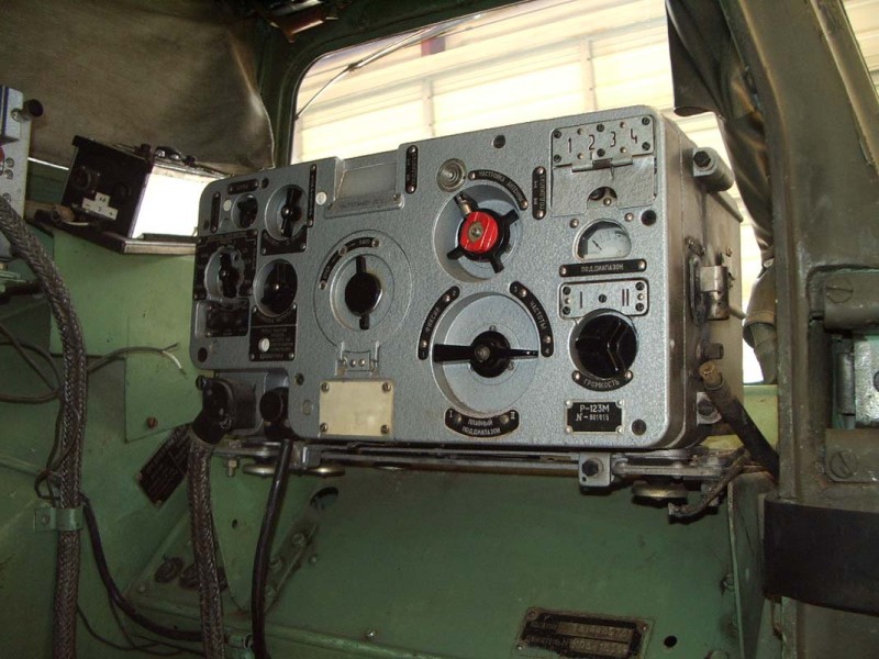
- post 2B12M ( 2B12M-1 ) - for control system checks;
- 2B26 console - for checking the automatic control system (emergency rocket explosion);
- heating panel of POG-6 head unit (POG-5, POG-5M);
- control panel 4A11-E2.1 Sb-1 (4A11-E2-II) - to measure the battery voltage of the missile head part, switching on the RD and control the serviceability of the circuits of the working windings of the EC;
- panel 9B151 - for checking the control system of the 3H8 product;
- 9B46MG ( 9B46M ) - for STR system check;
- unit P61502-1M (P61502-1) - for switching of radio sensor installations, control of their switching on, control of heating switching on and voltage of ampoule battery 1SB25M of 8F44G (8F44G1) products head part;
- 2V34 control system equivalent - to check the 2V12 post;
- the equivalent of the APR 2B27 system - for checking the 2B26 panel;
- special plugs: BREF K2.275 - for checking POG-6, BREF 9B154 - for checking 9B151, BREF-615 - for checking P61502-1M;
- Plug Sh72 and remote control 9B344 - to ensure the launch of the missile from the cabin or shelter.
To prevent the unauthorized use of nuclear weapons, the launch units equipped with the 2B12M-1 console were equipped with a code blocking device (9B362M1), which was stored separately from the launch units. The place under the CBU is to the left of the 2B12M-1. Installation of 9B362M1 in its normal place is carried out only when the missile brigade is brought to the highest alert by special command. The missile is not launched without unlocking the CBU. To unlock the 9B362M1, the H-O switch is moved to the "H" position (kit), the banners K1 and K2 light up. Then the six-digit number is introduced by means of the cipher set nodes. After that switch H-O is transferred to the position "O" (fire), at that banners K1 and K2 go out, banners C1 and C2 light up. If the code is entered incorrectly, switch H-O is not moved to the "O" position.
In the hiking position of the starting unit, the boom is in the lowered position, rests on the boom support and is locked, the table is raised and locked, the table supports are removed, the CA supports are raised, the grips are closed. The rocket is loaded onto the launch unit when the table is lowered and the clamps are open. The missile is lifted by crane, lowered to the launch unit underneath and secured with fittings and grips.
During the development of the wheeled launch unit 9P117 an attempt was made to abandon the use of a crane when loading missiles on the launch unit. For this purpose it was provided the possibility of craneless loading. The boom of the 9P117 launch unit had a complicated composite design. During the reloading, the 2T3 trolley with the missile was installed behind the launch unit. The launcher's boom was moved to the rear position, its upper part was folded back and laid on the rocket. This was followed by mounting the missile on the boom, loosening the missile from the bogie and placing the boom with the missile on the launch vehicle. Later on, craneless loading was refused, and to reload the missiles on the launch unit began to use a special vehicle crane 9T31M1. Due to the fact that craneless loading on the launch vehicles was no longer used, the complex design of the boom was also abandoned. The subsequent modification of the starting unit, which received the name 9P117M, had a monolithic welded boom, which simplified and cheapened the design.
The rocket is launched at the starting position as follows:
- the chocks of the starter unit are lowered
- the boom with the rocket rises to the vertical position (the table is locked)
- table stops are extended
- the rocket is secured with wind bolts (bolts rotate)
- open up arrow hooks
- the table is unlocked and the arrow is lowered and the missile remains on the table.
- By means of table supports and a pivoting mechanism, the missile is verticalized and aimed at the target
- with the help of the launch unit equipment, the rocket is checked, the rocket is filled with starting fuel, the ampoule batteries are used and the rocket is launched.
After starting, the starter unit is reset to its original position.
When the launch is cancelled, the compressed air is vented from the rocket, the starting fuel is drained, the rocket is placed in a camping position and the rocket is unloaded.
Laying of the rocket is carried out as follows:
- open up arrow hooks
- boom is upright
- table stays open
- fittings are screwed into the rocket's mounting holes
- grips are closed
- The wind bolts are unscrewed and placed in the sockets in the cabin.
- the arrow with the rocket goes down.
The missile is loaded from the launch unit to the trolley by crane.
Modifications:
- 9P117 - the composite boom provides the ability of craneless loading, the panel equipment for HF in nuclear equipment, high-efficiency BC 8F44 and chemical 3H8.
- 9П117-1 - added indicator block P61502-1 for chemical HF 8Ф44Г (8Ф44Г1).
- 9P117M is the same as 9P117, but with a monolithic boom.
- 9P117M-1 is the same as 9P117-1, but with a monolithic boom.
- 9П117М1-1 - post 2В12М-1 and 9В362М1 (CBU) installed.
Apart from armament of missile brigades of the 9K72 complex in the Soviet Union, the 9P117 (9P117M) units were widely exported (without panel equipment for special GPs and without CBU). Unlike the 2P19 (2P19-1) unit (tracked), the 9P117 allows the use of 8K14-1 missiles with 3H8 GP, allows the launch from the 9B344 remote control, many operations are mechanized.
Technical specifications
| Weight, kg: - rocket-powered - hiking |
37400 30600 |
| Dimensions, mm: - length - width - hiking altitude - altitude at war |
13360 3020 3330 13670 |
| Fitting into the railway dimension: - via USSR railways - Western European countries |
dimension 1B dimension 02-T |
| Center of gravity position, mm: - from the ground, mm: from the ground - from the front end |
1720 6400 |
| Management | semi-automatic, manual redundancy |
| Engine | |
| Type | D12A-525A |
| Power, at nominal rpm 2100 rpm, HP. | 525 |
| Moving data | |
| Tires with automatic pumping: - size - normal pressure, kgf/cm2 - minimum pressure, kgf/cm2 |
1500х600х635 3.5 1.0 |
| Base (distance between axes 1 and 4), mm | 7700 |
| Number of driving axles | 4 |
| Maximum axle load for rocket transport (axle 4), kg | 10000 |
| Track width, mm | 2375 |
| Turning radius on the outer wheel track is minimal, m | 13.5 |
| Passage corridor, m | 6.5 |
| Corner of entry, deg. | 28 |
| The corner of the convention, deg. | 25 |
| Angle of override, deg. | not more than 18 |
| Transverse roll angle, deg. | not more than 15 |
| The width of the ditch to be overcome, m | 2.5 |
| Power reserve, km: - when driving on an asphalt highway for fuel consumption control. - on the dirt road, practically fuel |
not less than 650 not less than 500 |
| Power Sources | |
| Diesel-electric unit APD-8-P/28-2: - number - power (rated), kW - rotational frequency, rpm - current type - voltage, V |
1 7 1500 permanent 28 |
| Generator GDL-10: - number - power, kW - rotational frequency, rpm - current type - voltage, V |
1 10 3600 - 5750 permanent 28 |
| Rechargeable batteries: - type - SA volume - vehicle number - voltage, V |
12-SТ-70 2 4 24 |
| Hydraulic system | |
| Pump 0405/8E35: - number - drive - output, l/min |
2 one from the ADF, the other from the car's PTO. 18 |
| Maximum pressure in the hydraulic system, kgf/cm2 | 165 |
| Hydraulic jacks, quantity | 6 |
| Working fluid (AMG-10 oil), kg | 135 |
| Oil tank, l | 55 |
| Time of lifting the boom to the vertical position, min. - unmissile - rocketed |
2.0-3.5 2.25-3.5 |
| Time of lowering the boom to the hiking position, min. - unmissile - rocketed |
3.0-4.4 3.0-4.0 |