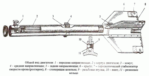
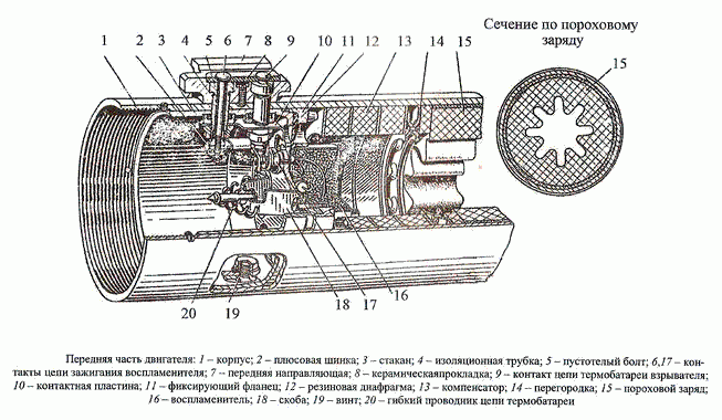
Casing 1 of the engine is a hollow cylinder made of aluminum alloy. There is a thread on the inside of the casing at the front side for connection to the fourth bay, and on the outer surface with two hollow bolts 5 is attached to the front guide 7. The case at the front side is closed with a glass 3, which is attached with a screw 19 and bolts 5. The glass is designed to attach the ignition 16 and the contact device of the battery of non-contact fuse. The inner cavity of the motor is sealed with a rubber diaphragm 12, which is pressed to the glass 3 with the flange 11.
The igniter 16, designed for solid fuel ignition, consists of a hermetic thin-walled case filled with coarse black powder. There are two electric fuses in the swirled cover of the case. Plus wires of fuses are connected to contact 17, minus outputs - to the case. Pin 17 is connected with pin 2 to pin 6, located inside hollow bolt 5. Contact 6 consists of a brass rod, electrically isolated from the hollow bolt by ceramic spacer 8, insulating tube 4, rubber and ceramic bushings.
Charge 15 is made of NMF-2 solid fuel containing K2 SO4 salt additive to reduce the impact of the engine jet on the aircraft carrier. The charge is a single-channel cylindrical draughtsman with an 8-beam star-shaped inner channel. The outer surface of the charge is wrapped with a thermally insulating plastic tape that protects the charge from mechanical damage and acts as an armour. The same functions are performed by rubber rings glued to the ends of the charge. Burning of the charge only on the inner surface reduces the thermal load on the engine housing walls. The star-shaped shape of the charge allows for approximately constant pressure in the chamber. The charge is inserted inside the engine casing as far as it goes into baffle 14, which serves to equalize the pressure on the outer and inner surfaces of the charge. This is necessary to prevent charge failure. The linear expansion of the charge is compensated by compensator 13. It is a package made of microporous rubber and cardboard washers.
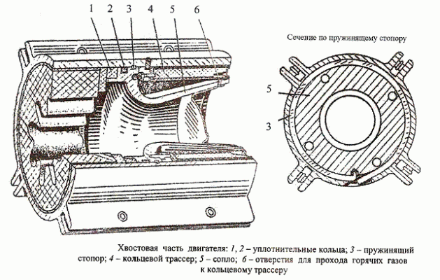
Nozzle 5 of the engine is made of steel. It is connected to the housing by means of a rectangular stop 3. The stop with the bent end through a rectangular slot in the motor casing is inserted into the blind radial hole of the nozzle and by rotating the nozzle is tightened inside, located in the combined ring ducts of the casing and the nozzle. The nozzle is sealed with a rubber ring 2. The second rubber ring 1 is used to seal the charge. Inside the nozzle is a thin-walled aluminum plug that seals the engine. Thanks to the plug in the engine, the pressure in the engine is maintained until the moment of starting, corresponding to the moment of assembly.
In the tail end of the engine there is a circular tracer 4, which provides the possibility of observing and fixing the missile's flight path. The tracer consists of pyrotechnic composition pressed into a special housing. Burning time is at least 23 s. The color of the tracer is orange. The track is flammable from the gas jet of the engine. For this purpose three holes 6 are provided in the nozzle.
At the tail end of the case at an angle of 90° to each other are the ribs with longitudinal grooves to install the wings. There are five screw holes each in the ribs that fix the wings to the motor casing. A rear rail is mounted between the wings. It is fastened with four screws.
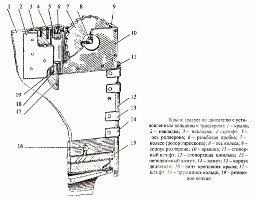
The wing is shaped like a rectangular trapezoid. The thickness of the wing is constant throughout the entire wingspan. The front edge is arrow-shaped and pointy. In the lower part of the wing are five holes with slots for passage of screws 16 wing fasteners. At the end of the wing there is a rolleron that is locked with a pin 12. To the wing are attached pads 2 and 3. The first limit the angle of rotation of the rolleron, the second fix the axis 5 rolleron.
Rolleron limits the angular speed of the missile roll. It consists of the body 9, axis 5, wheel (gyro rotor) 7 and cover 10. In the case of the rolleron installed pin 11, in the groove which includes a locking pin 12. pin keeps the rolleron fixed while the rocket motor is running. Spring 3 is held in a compressed state by a fusible filler 5. When the engine is started, the filler melts, the spring presses the stud and the roller is released.
Technical specifications
| Total traction pulse, Ns. | not less than 38100 |
| Drag, N: - maximum - minimum (at charge temperature -54°C) |
25000 10000 |
| Engine running time, s: - at charge temperature of +60°C - at a charge temperature of -54°C |
1.7 3.2 |
| Maximum pressure in combustion chamber, N/m2 | 13.106 |
| Charge length, mm | 1570 |
| Outer diameter (with reservation), mm | 118 |
| Charge weight (with reservation), kg | 20.5 |
| Uncharged engine weight, kg | 14.8 |


