The 9M114 anti-tank guided missile is designed to destroy modern tanks and other armoured targets, as well as small ground targets (DOT, DZOT, etc.) and low-flying air targets (helicopters, low-speed aircraft) of the enemy. The 9M114 projectile is used for firing from the 9K113 complex, placed on the Mi-24 helicopter, from the 9P149 and 9P133 fighting vehicles.
Composition and general layout of the projectile
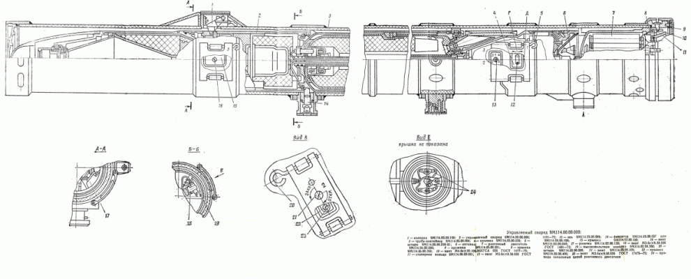
Guided projectile 9M114 is a single layout, structurally consisting of three parts: the guided projectile 2 (Fig. 1), acceleration engine 7 and the starting tube-container.
1-block, 2-controlled projectile 9M114, 3-pipe container, 4-cap, 5-pin, 6-antenna, 7-engine, 8-spring, 9-cap, 10-screw, 11-lock ring, 12-screw, 13-axis, 14-locker, 15-cover, 16-screw, 17-socket, 18-screw, 19 high-voltage block, 20-pin, 21-screw, 22-cover, 23-screw, 24-wires of ignition plugs of the overclocking engine.
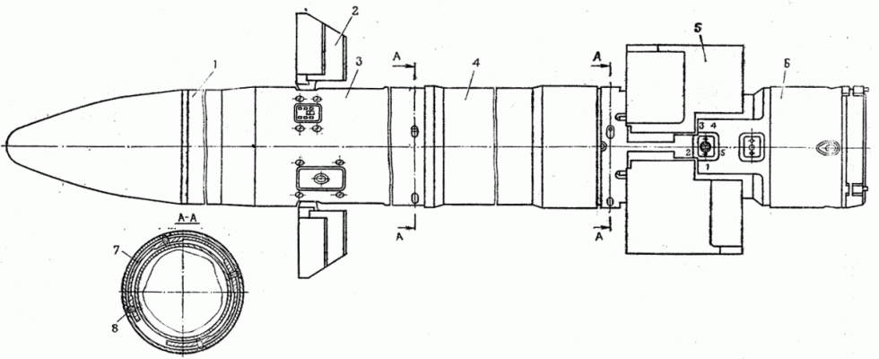
The guided missile is made according to the aerodynamic scheme "duck" and structurally consists of a combat unit 1, the steering compartment 3, the engine unit 4, instrument compartment 6. Four arched quills 5 serve to create the necessary lifting force, and the control aerodynamic force is created by deflection of the aerodynamic rudders 2. To ensure launch from the launch tube, the projectile has no protruding parts, the rudders and feathers are folded up and open after the projectile has departed from the launch tube.
1-st combat unit 9H132, 2-rudder, 3-rudder compartment, 4-engine unit, 5-feather, 6-dash compartment, 7-lock ring, 8-screw.
- The combat unit (see description) is located in the front of the projectile and is a self-contained, hermetically sealed unit that allows for multiple threaded joints with the steering chamber. The combat unit housing contains a cumulative charge, a piezo generator and a safety executive mechanism of the explosive device.
- The steering compartment (see description) is located behind the combat unit. The steering compartment contains projectile controls, units for formation and execution of commands for control and power supply of onboard equipment of the projectile. The steering compartment is connected to the propulsion system by means of a locking ring 7 and four screws 8.
- In the central part of the projectile there is a propulsion system (see description), which is a single-chamber double-mode motor with two side sloping sockets. The propulsion system contains a 9X183 marching charge, a 9X261 marching charge igniter and a tube. The engine unit is connected to the instrument compartment by means of a locking ring 7 and four screws 8.
- Behind the engine unit there is an instrument compartment (see description) . The instrument compartment contains the on-board radio unit and the defendant's unit. Four arched nibs are placed on the instrument compartment housing. Antenna 6 (Fig. 1) of the onboard radio equipment unit is located in the tail of the projectile.
- Behind the instrument compartment there is an overclocking engine 7 (see description). The overclocking motor is a single-mode solid fuel engine. It accommodates the ejection charge 9X184 and the igniter 9X262 of the ejection charge.
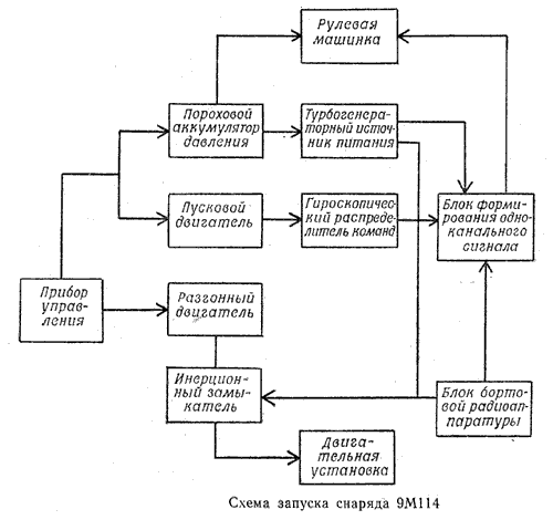
The guided missile is used as a shot and is placed in a plastic launch tube container. The projectile is supported by the centering belts of the propulsion system on the inner walls of the launch tube-container and is held against movement by a clamp 14, screws 10 and a locking ring 11. The projectile is electrically connected to the launch tube-container by the block 1, which is disconnected at the moment of firing, as well as by the wires of 24 ignition circuits of the accelerating motor. After the operator has pointed the sight at the target and pressed the RUN button on the operator's console, the turbo-generator is started and the on-board equipment is fed, the gyroscopic distributor enters the operating mode and after 1 with the start of the overclocking engine. Under the action of the emerging thrust of the acceleration engine, getting a rotational motion and initial speed, the projectile takes off from the container tube. After the projectile leaves the tube-container from the electric impulse of the turbo-generator power supply, the propulsion system is activated, which accelerates the projectile to supersonic speed. Due to the difference in speed between the projectile and the EP, the EP is separated from the projectile and falls to the ground. After the projectile leaves the container tube, the centrifugal forces cause the rudders and arched feathers to open and stop in the open position. The projectile is controlled by a command radio line, during which the operator keeps the mark of the sight on the target. The control system automatically holds the projectile on the sighting line. When the projectile encounters the target, it triggers an explosive device, detonates the charge of the combat unit, pierces the armor and hits the target.
Guidance of the projectile at the target.
Homing of the projectile at the target is carried out by a semi-automatic control system, the principle of which is that the withdrawal and retention of the projectile on the line of sight before hitting the target is done automatically with the help of the control system equipment placed on the carrier (helicopter, combat vehicle). The operator's function in a semi-automatic control system is to combine the mark of the sight with the target.
The deflection of the projectile from the line of sight is measured by the direction finder of the 9P149 war machine control or 9K113 complex, which perceives the pulsed infrared radiation of the light source mounted on the projectile. The sight and direction finder are structurally combined into a control unit and have a common optical part. The direction finder signals in the form of stresses proportional to angular deviations of the projectile from the line of sight in the horizontal plane (course) and in the vertical plane (pitch) are received by the command development unit, where they are transformed into control commands taking into account changes in aerodynamic characteristics of the projectile during the flight in the form of stresses proportional to linear deviations of the projectile from the line of sight at the course and pitch. Control commands at the rate and pitch from the team-building unit are transferred to the radio equipment for transmission of commands, placed on the carrier, and in an encrypted form are transmitted over a radio line to the projectile.
Control commands received by the onboard equipment of the projectile are decoded and converted into a single-channel control signal received by the projectile steering machine.
Principle of formation of a single-channel control signal on board the projectile
The projectile uses a single-channel control signal conditioning system, which allows to create the control torque required to change the position of the projectile in two planes, only one relay actuator - the steering machine with two steering wheels, located in one plane. The actuating force is generated for each revolution of the projectile by forced rotation around its longitudinal axis. The initial rotation of the projectile is created by the acceleration motor when moving in the starting pipe-container. The projectile rotation speed is maintained in the trajectory by means of the aerodynamic shape of the feathers. The executive body is a system consisting of a relay steering machine and two steering wheels located in the same plane. An alternating signal is emitted to the steering machine windings. According to the polarity of the signal supplied, the rudders can deviate to one of the two extreme positions. In flight, the deflected rudders create a control aerodynamic force that unwinds the projectile at the desired angle in the desired direction. The actuating force causes the projectile to change its position relative to the line of sight. As the projectile rotates, the vector of aerodynamic force control also rotates relative to its longitudinal axis. And in order to obtain the control force of the required magnitude and direction, it is necessary to deflect the rudders from one extreme position to the other (to move the rudders) synchronously with the rotation of the projectile. Creation of the control aerodynamic force occurs during each rotation of the projectile around its longitudinal axis. The single-channel signal is generated in the single-channel signal conditioning unit. The command gyroscopic distributor includes a three-stage gyroscope, phaso regulator and potentiometer. The gyroscope provides information on the angular position of the projectile when it rotates. The angle of rotation of the projectile starts from the arched position of the gyroscope, i.e. from the position that the projectile occupies in the starting pipe-container.
Launching the projectile

When the RUN button located on the control unit is pressed, constant voltage is applied to the contacts of the projectile launch connector through the contact device of the starting pipe-container from the onboard network of the carrier. Depending on the polarity of this voltage the corresponding code is automatically set in the on-board radio unit.
When the gunpowder pressure accumulator and the starting motor are triggered, their charges ignite. The powder gases of the starting motor are fed into the acceleration rotor of the gyroscopic command distributor. Powder gases of the powder pressure accumulator are fed through a filter to the steering machine and to the acceleration of the rotor of the turbine generator. Turbo-generator after 0.7 s goes to the mode, supplies alternating voltage to the CV unit, from which supply voltages are fed to the equipment of the projectile. In 1 s after pressing the Start button, the delay unit of the panel starts the DC voltage to the contacts of the electric igniter of the overclocking engine. When the overclocking motor igniter is triggered, its charge is ignited. The thrust of the accelerating motor causes the projectile to advance in the starting pipe-container, bending of pins, unraveling of the gas-dispensing system, triggering of the contactor, dismembering of the projectile with the fork of the board removal of the starting pipe-container, breaking of the ignition circuits of the accelerating motor. After activating the contactor, alternating voltage from the turbo-generator power source is supplied to the electric igniter of the delayed action of the remote control.
When the projectile moves through the starting pipe-container, the inclined nozzles of the accelerating motor force the projectile to rotate around its longitudinal axis. The thrust of the acceleration engine causes the projectile to fly out of the launch tube, destroying the lid at the front end of the tube. After the projectile leaves the launch tube, the rudders and feathers are opened by centrifugal forces. The accelerating engine is separated from the projectile, the electric igniter of slow action supplies the flame force to the remote control igniter, which ignites the charge 9X183 of the engine unit.
At a distance of 20-100 m from the cut of the starting tube-container the explosive device of the combat unit is detonated (connection of the electric circuit of the piezo generator to the electric circuits of the safety detonator).
Action of the projectile in flight
When the projectile is encountered in the field of view of the direction finder of the control device and in the field of high-frequency radiation of the command radio line transmitter the onboard receiver of the projectile receives microwave signals. The detected and amplified clock pulses are time delayed by a special circuit and are received for launching the IR projectile transmitter. IR pulses from the transmitter are received by the direction finder, whose receiver opens precisely when the transmitter's IR signals arrive. The receiver is built from the clock pulses of the radioline equipment mounted on the carrier.
The direction finder determines the deviation of the projectile from the sighting line and generates control commands, which are transmitted through the communication line to the projectile. Control commands, received and decoded by the onboard radio equipment unit, are received by the single-channel signal generation unit. The formed single-channel signal is fed to the electromagnets of the steering machine that drives the aerodynamic rudders.
The control force at the rudders is generated in one revolution of the projectile. The control force causes the projectile to change its position in space, so that the projectile is pointed at the target along the sighting line.
When the projectile encounters the target, the piezo elements are compressed, and the resulting stress on the elements triggers the detonator and then detonates the entire explosive charge contained in the warhead. The cumulative jet generated by the engagement of a combat unit pierces the armour and hits the target.
Tactical and technical characteristics
| Maximum range of controlled flight, m | 5000 |
| Average flight speed, m/s | 350-400 |
| Departure velocity from the pipe, m/s | 55 |
| Caliber, mm | 130 |
| Length, mm | 1830 |
| Mass with launch tube-container, kg | 46.5 |
| Armour penetration at 60° from normal to armour, mm | 280 |
| Time required to start the guided projectile (from the moment the trigger is pressed to the beginning of projectile movement), s | not more than 1 |
| Range of heights of projectile combat application | range from 0 to 3000 above sea level |
| Temperature range of projectile warfare, °С | ±50 |
| The dimensions of the capping, mm: - length - altitude - width |
1977 367 331 |
| Mass of the capping with the projectile, kg | 80 |
1. Управляемый снаряд 9М114. Техническое описание и инструкция по эксплуатации. 9М114 ТО. Военное издательство МО СССР, М.,1982г.
2. Изделие 9С446. Техническое описание. Часть 1. М.: Воениздат, 1980. - С.4.

