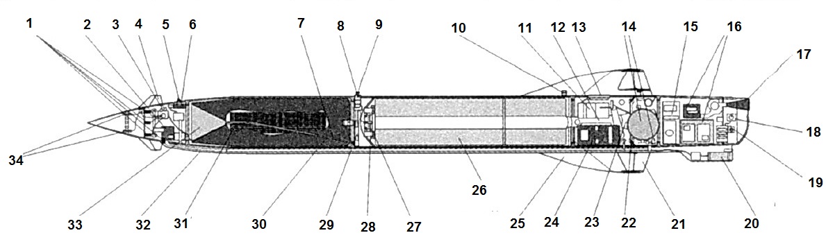
- touch probe system SKD-24
- steering machines and steering gears
- forced steering wheel housing
- steering surface
- PM-68 fuse warp circuit check
- safety mechanism PM-68 (PIM)
- electric tube from KFOR-24 to PIM
- engine contacts
- front bugle
- rear bugle
- electrical automation units
- gas duct
- mating part of the breakout connector Osho-4
- compressed air cylinder Air and fittings unit (AAB)
- autopilot
- radio equipment units receiving control commands "Delta-P1M"
- receiving antenna of Delta-P1M equipment
- channel switching units
- Delta-P1M control socket
- T-60-9 motorway
- aileron
- aileron drive
- motor nozzle socket
- power supply unit (thermal battery)
- wing
- solid propellant rocket engine PRD-228
- igniter
- UDP2-3 pyropatroons
- fail-safe mechanism I-256
- F-23M fragmentation-combatant combat unit
- cubic shrapnel elements (glued on the sides of the BC)
- fairing
- steel conical shaped funnel
- linear accelerators
Linked materials: