The non-contact fuse is located between the warhead and the engine and is an incomprehensible hermetic structure, which is an independent compartment of the missile. The detonator reacts to the target's heat radiation and initiates a warhead detonation when the missile flies near the target or a rocket self-liquidation in the event of a miss.
The fuse consists of:
- electronic optical unit,
- power supply battery,
- safety mechanism.
Electron-optical unit receives and converts the target's thermal radiation and outputs a signal to the PIM fire circuit at the required moment. The power supply battery is a chemical source of current. One of its features is that at normal temperatures its electrolyte is in solid state. This ensures that it is stored for a long time. To power the battery the electrolyte must be melted. Therefore, the battery is equipped with a pyrotechnic heater, when triggered, it generates thermal energy that warms the battery to a temperature of 400-600 ° C. The pyrotechnic heater is ignited by the current pulse from the aircraft-carrier board, through the contact system installed on the rocket engine.

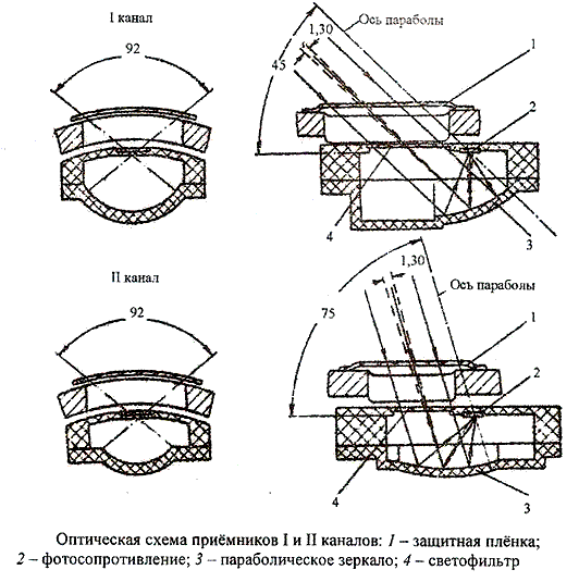
The optical system of the fuse consists of radiant energy receivers providing a circular view in two directions: at an angle of 45° (channel 1) and 75° (channel 2) to the axis of the missile in the direction of flight. Each channel consists of four receivers. The angle of view of each receiver is 1°30'. The receivers of both channels are located on the same circle (through one) of the fuse body. The presence of two channels of the fuse provides its high noise immunity. The fuse is triggered only when two pulses come from the optical system in a certain order (first by the 1st channel, then by the 2nd channel) and at 0.1s intervals. Each receiver consists of a photoresistivity 2, which converts the radiant energy into electrical energy, a parabolic mirror 3, which focuses the radiant energy on the photoresistivity, a light filter 4, which detains all the beams, the spectral composition of which is different from the target radiation, and a protective film 1, which protects the receiver from the environment.
The Safety Execution Mechanism (PEM) has the following functions:
- provides a long-range detonation of the fuse;
- emits a signal to detonate a combat unit when it receives a signal from an electronic optics unit;
- self-liquidates the missile in the event of a miss;
- ensures the safety of missile maintenance.
The PIM principle of operation is based on the use of inertial forces acting on the axis of the fuse. It uses two clockworks to coordinate the processes occurring in the PIM in time.
The PIM electro-kinematic circuitry includes:
- fire chain safety mechanism
- safety mechanism
- block jumper
- inertial contact
- flammable contact device
- a liquidator.
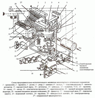
The fire chain includes electrodetonator 26, capsule-detonator 8, which is a link in the fire chain. The detonator capsule is mounted in the radial opening of disc 21, so the fire chain remains broken until the disc is turned to the required angle. A jumper (shunt) 22 is used for the same purpose. It is activated in parallel with the electrodetonator 26 and makes it impossible for current to flow through it. The jumper is broken at the end of the drive 21 by means of the stud 11 mounted on the drive.
The inertial-safety contact consists of movable (23) and fixed (25) contacts and springs 24. At the active section of the trajectory, under the action of inertia forces, contacts 28 and 25 close and shunt the combat (ignition) capacitors C22 and C23 with low resistance. In this case, the voltage on the capacitors drops to a value at which the triggering of electric detonators is impossible.
The contact ignition device consists of a pyrotocollator 12, slide 6, spring 13, plate 7 and contact 5 located on disk 21. Through the finger 14, the slider is connected to the plug of the 15-hour mechanism 18 of the self-liquidator. The other end of the slider is resting on stop 4 of inertial fuse 27, so it is possible to move the slider only after the fuse 27 to the leftmost position. The pusher is triggered when its electric circuit is closed by contact 5 and the slider projection 6. The energy of the powder gases moves the slider upwards. This opens up the possibility of further rotation of disk 21 and starts the clockwork 18 of the liquidator. Plate 7 stops slider 6 in the upper position.
The self-liquidator consists of movement 18, threaded bushing 17, contact plate spring 16 and fork 15. The watch movement has a crown spring. A bushing 17 is fitted on one end of its axis, which acts as the mainspindle. As the screw rotates, the bushing moves in the direction of the hand. At the end of its movement, the leaf spring 16 closes the electrical circuit, which includes ignition capacitors and an electrodetonator. The self-liquidator movement is started by a slide 6 which releases the first one when turning the fork 15.
The procedure of PIM operation is as follows. At the active section of the trajectory the missile experiences an overload in the direction reverse to the flight direction. Under the action of overloads fuse 27 releases the disc 21. The same overloads cause the disc to rotate. The rotation speed is controlled by a long-range clockwork mechanism 19. When the contact 5 of the rotary disc with the lug of the slide 6 is closed, the pyrotocollator 12 is triggered by moving the slide 6, the disc 21 can be further moved and the clock mechanism 18 of the liquidator is started. At the end of the swivel disk pin 11 breaks off the tongue 22, thereby connecting the electrodetonator 26 to the combat (ignition) capacitors C22 and C23. In the raised position, the disk is locked with a clamp 20. The capsule-detonator 8 in this case is installed in one line with the electrodetonator 26 and the transfer charge 9. The fire circuit becomes closed.
At the end of the active section of the trajectory, after the overloads have stopped, spring 24 closes contacts 23 and 25, bypass resistance 45 is switched off and capacitors C22 and C23 are charged to the level required for triggering the electrodetonators. The detonator comes on full alert. When flying close to the target, the electro-optical unit generates an impulse that unlocks the electrical circuit through which the combat capacitors are discharged into the electro detonator 26. The detonator detonates the missile's warhead. In the event of a miss, the discharge circuit of the capacitors is closed by the self-destructor.
Technical specifications
| Response range at relative rapprochement speeds of 150 - 3000 m/s | 0 – 9m |
| Fuse Ready Time | 0.1-0.8s after the end of engine operation |
| Self-liquidator response time | 21-23 s from the moment the missile is launched |
| Overall dimensions, mm - diameter - length |
127mm 181mm |
| Weight | 3.1kg |
