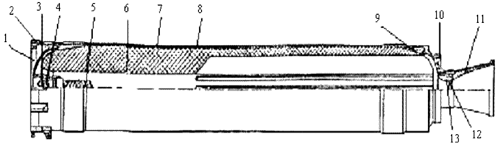
- the bottom of the front with a thermal protection bowl;
- power stem;
- pressure switch;
- pyropatrons;
- ignitor;
- solid fuel charge;
- hull;
- heat protection coating;
- rear bottom with heat-protective bowl;
- landing belt;
- nozzle block;
- stopper;
- liner.
The rocket engine is a dual-chamber single-chamber solid propellant rocket engine (SPRT) and consists of:
- case, which includes the cylindrical part 7, front bottom 1, rear bottom 9 and nozzle block 11 with insert 13 and plug 12:
- solid fuel charge 6 - a single-channel mixing fuel ball with slotted cuts on the engine nozzle side. Presence of eight slots allows to increase essentially a burning surface of fuel and to provide a starting mode of engine operation. On the march mode after the charge is burned out in the gap area, combustion is carried out only on the surfaces of a single-channel draughtsman;
- igniter 5 with two pyropatrons to ignite the igniter and pressure indicator 3 in the combustion chamber. All elements are located at the front bottom of the engine housing. The alarm device is used in the protection system of combat equipment to issue a command to start a radio detonator. The second squadron is used to duplicate the engine start. The duplicating pyrotechnic is triggered one second after the engine is started, providing ignition of the ignition in case the first pyrotechnic fails.
The front and rear bottoms (elliptical shape) of the body are made of high strength steel. At the external cylindrical part of the bottom are threaded special thrust threads and drilled shoulder, with which when screwing the bottoms are centered relative to the front strap and the thickening of the rear end of the cylindrical part of the body.
Cylindrical part of the body is a thin-walled cylinder 7, made of high-strength sheet steel, to the front end of which welded power strap 2. Ten bosses are placed on the power strap and a special thrust thread is cut for screwing the front bottom. The bosses, made as a unit with the bends, have threaded holes and studs for connection to the dashboard compartment of the rocket. In the thickening of the cylindrical part of the rear end also cut a special thrust thread for screwing in the nozzle block, drilled holes for docking to the wing block compartment.
To the rear bottom the cylindrical seat belt 10. on which the bearing of the fifth compartment is installed, and the cylindrical nozzle, in which threads for turning the nozzle block are cut. The tightness of the inner cavity of the motor housing during storage and operation is ensured by pressing rubber gaskets between the cylindrical part and the dinchamber. The gaskets are pressed by the front bottom and nozzle block during assembly. The joint of the ignition block is sealed with a copper gasket. On the inside, a rubber bag is glued to the cylindrical body, which acts as a protective layer 8 between the motor housing and the charge. In the front and rear parts of the bag has thickened in the form of cups designed to provide the required stress-strain state of the charge at temperature fluctuations.
The rear bottom has an outside seating area for the wing section bearing and a thread for attaching it. On the inside there is a thread for installing the nozzle. The nozzle consists of a housing with a cylindrical threaded part and a tapered output. The critical cross-section of the nozzle is formed by the nozzle insert, which is screwed into the housing. Graphite insert is glued into the inner cavity of the body from the rear bottom, tightness of joints when assembling the nozzle block is provided by rubber gaskets.
A glass is welded in the center of the front bottom, which has seats for the installation of pyropropatrons, as well as internal threads for the installation of the ignition housing. In the spherical part of the front base is welded connection for the installation of the pressure indicator. The igniter consists of three cylindrical rods of solid fuel and a coarse-grained smoke gunpowder hood, encased in aluminum cases and placed in a mesh housing. The casing of the ignition, attached to the front bottom, partially enters the charge channel. Two pyropropatrons provide reliable ignition response.
Motor operation starts from the moment the launch command in the form of current (+27V) is given to the pyropropatron wire bridge through the electrical circuit of the rocket system. The wire bridge is instantly inflamed, igniting the ignition composition of the pyropropatron and its pyrotechnic composition. The resulting gases, breaking through the bottom of the pyropropatron, ignite the main ignition hanger. The mass of the formed gases and their thermal energy is enough to create the necessary conditions for the ignition of the fuel charge and its sustainable combustion. The combustion of the charge occurs through the inner channel, slots and ends. Pressure in the chamber at the starting mode is not more than 1.5 kPa. Engine traction on starting mode ~ 3200 kgs. Engine running time in start mode ~ 4s. in marching mode ~ 8s. Total engine run time ~12s.