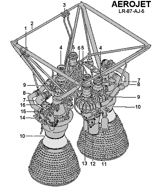
- control connector
- power frame ;
- drainage flange;
- oxidizer pump ;
- fuel pump ;
- gas generator ;
- the pipeline of an input of an oxidizer in the combustion chamber ;
- pipeline of fuel supply to the combustion chamber;
- turbo-pump unit (TNA);
- combustion chamber;
- fire extinguisher;
- exhaust pipe of TNA;
- heat exchanger of TNA lubrication system;
- pressure sensor;
- fuel throttle valve;
- oxidizer throttle valve;
Linked materials: