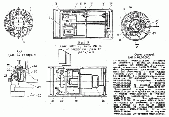
The steering compartment is designed to accommodate units that are part of the on-board control equipment, as well as power and gas sources.
In the housing 10 of the steering compartment is fixed by inserts 8 with screws 7 of frame 20, on which the following blocks are mounted:
- the steering group;
- steering wheel 11;
- single-channel signal conditioning unit 6, control socket 3, ignition circuit block 4 with inertial contactor 5 and board 2 for communication with the instrument compartment equipment;
- gyroscopic distributor of commands 18;
- turbogenerator power supply (turbogenerator 19 and stabilized rectifier 9) with high voltage block /;
- gunpowder pressure accumulator 15;
- starting engine 13.
The steering group consists of rudders 25, reinforced on axles 26 in stands 23 with bearings 22, cages 21, locks 24, springs 27, 28, locks 12. Powder pressure accumulator, turbo generator, steering machine are connected to each other by gas tubes 16, 17.
On the case of the 10 steering compartment is also mounted balancing weight 14.
Electrical connection of the steering compartment blocks is carried out with the help of boards through the onboard control socket 3.
Turbo-generator power supply
Turbo-Generator Power Supply (TGIP) is designed to supply power to the projectile's on-board equipment. TGIP provides the following output characteristics:
- voltage +1700 V;
- voltage -27 V;
- voltage +12.6 V;
- voltage -12.6 V;
- voltage +260 V.
Time of TGIP output to the mode does not exceed 0.65 sec. Structurally TGIP consists of two independently made blocks: turbogenerator (TG block) and stabilized rectifier (BlockSV). Functionally TGIP is a part of PAD - RM - TGIP system. Primary energy source on board the projectile is energy of powder gases PAD.
Powder pressure accumulator
Powder pressure accumulator is designed to supply the powder gases of the steering machine and the turbo-generator power source during the flight of the projectile.
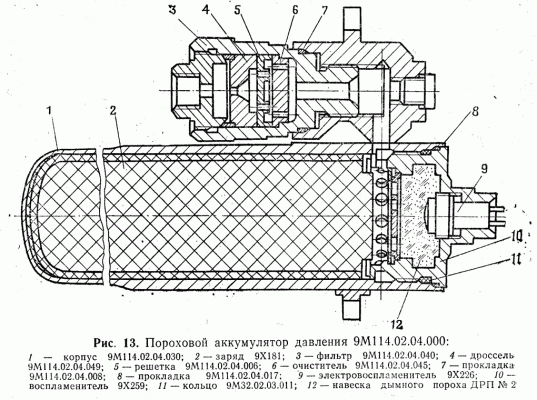
The PAD consists of a housing 1, which is a combustion chamber, and a filter 3, which purifies the gas from solids by means of cleaner 6 and grid 5. Gas flow rate and internal ballistics parameters are determined by the throttle orifice 4. Inside the PAD case there is a charge of 2 powder pressure accumulator (charge 9X181), reserved on the cylindrical surface and spherical end. A igniter 10 of the powder pressure accumulator charge (igniter 9X259) is screwed into the PAD case, which consists of an electric igniter 9 and a smoke powder hanger 12 (CPSD No. 1 and DPD No. 2). Gaskets 7, 8 and ring 11 ensure a tight assembly.
The PAD works as follows. From an electrical impulse from the carrier is triggered by an electric ignition, igniting the gunpowder hood, the force of the flame which ignites the charge 9X181. Powder gases produced by the combustion of the 9X181 charge pass through the filtration system, throttle, gas supply tubes and enter the cavity of the steering gear spool and turbine generator. When gunpowder gases enter the cavity of the tailgate spool, they drive the tailgate piston, which provides the angular movement of the steering wheels necessary to control the projectile. In addition, the powder gases rotate the turbine, and with it the rotor of the turbine generator, which is the onboard power supply.
Starting engine
The starting motor is designed to accelerate the rotor of a gyroscopic device to the required speed.
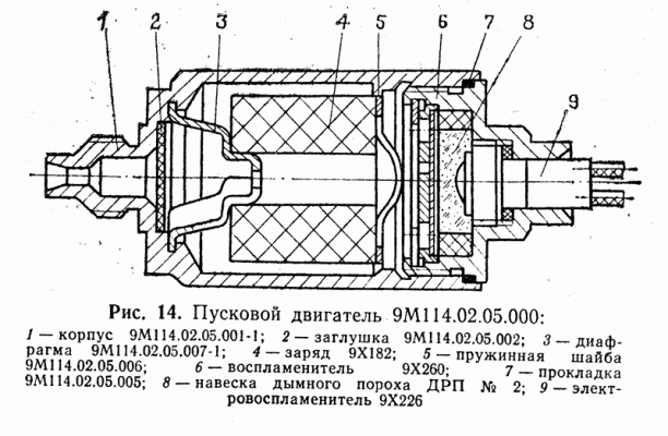
The PD consists of a housing 1, which is a combustion chamber, charge 4 starting engine (charge 9x182), vos-"fender 6 charge starting engine (igniter QX260), aperture 3 and spring washer 5. Ignition 9X260 6 consists of the attachment 8 smoke powder and electric ignition 9. Gasket 7 and plug 2 ensure tightness of assembly.
The AP works as follows. Electric ignition is triggered by an electric impulse, igniting the attachment of the smoke powder, the force of the flame which ignites the charge 9x182. Powder gases produced by burning 9x182 charge come to the rotor of the gyroscopic device, providing the acceleration of the rotor to the required rpm.
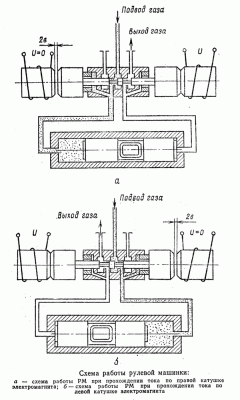
Steering machine
The steering machine is designed to deflect aerodynamic rudders from one extreme position to another, which is necessary to control the projectile.
The steering machine is a gas-fired electric signal booster and operates in relay mode.
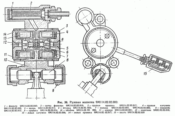
Steering machine consists of a cage 10, in the tide of which is a working cylinder with a piston 8, covered with lids 9, and a fine filter 1, which uses a mesh 2 as a filter element.
In the clip is the body 11 with a spool distributor, consisting of a set of rings 7, pressed into the body, chetyrehromochnogo spool 12, two bushings 6 and screwed on the spool two anchors 5.
Two coils 4 and 13 of electromagnets are placed in the body, covered with right 3 and left 14 caps. The outputs of the coils are soldered to the board 15.
As a working body for the steering machine are used gases of the powder pressure accumulator, which are fed through a fine filter to the spool and from it through the channels under the steering machine piston. When command signals are given, current flows alternately through one or the other coil of the electromagnet.
When current passes through the left spool 13 of the electromagnet, the armature 5 with spool 12 is attracted to it by the gap of 2v between the armature 5 and the left cover 14 and opens the gas passage to the right cavity under the piston 8, so the piston moves to the leftmost position. At the same time, the gas enters the working cavity under bushing 6 on the right side, creating an effort to return the spool with the anchor to the neutral position. But this force is less than the force of attraction of the anchor by electromagnetism-nite, and as long as the left coil carries current, the spool with the anchor will be held by the electromagnet in the left position.
As the current passes through the right coil of 4 electromagnets, the process described above is repeated, but in the opposite direction.
When the steering machine is operating, the piston takes one of the two extreme stable positions. The progressive movement of the piston through the lead, the end of which is inserted in the piston slot, is converted into an angular movement of the steering wheel.
