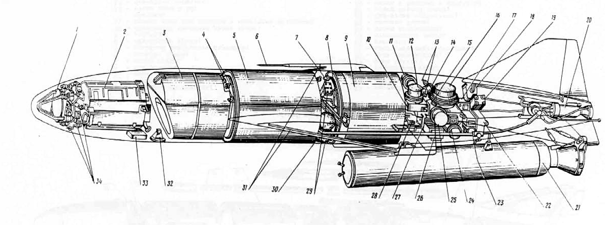
- DC-1SE antenna device
- DC-11SE unit container
- combat unit
- 4B701 fuse
- "O" tank
- air pressure receiver PVD-5
- pressure switch in the chain of switching of the marshalling engine operating mode SDU-4A-0.75
- folding mechanism
- G-compartment tank
- electrical switchgear
- control gyro
- damping gyro unit DP-5
- mechanical switches TVK-22000
- electric breaker unit (plug) AERU-129-2VR-47
- DVM-A software device series 1
- control unit DP-2P
- appliance 30815
- steering gear DP-4A
- steering gear DP-4A
- marshal engine C2.722V.0000-0
- starting engine SPRD-192P
- converter control box KU-1500-VT-3I
- PT-125C converter
- PA-1500-WT-3I converter
- integration gyro unit DP-6B
- radio transmitter transmitter
- 52C ampoule battery
- roll steering machine DP-4A
- air units
- receiving antenna of the radio altimeter
- 30822 sensors
- transmitting antenna of a radio altimeter
- software mechanism DVM-R
- sensor box 30825
Linked materials: