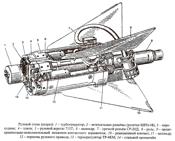
The steering compartment has a cylindrical body with two pairs of steering wheels on the outside and a steering linkage on the inside. The steering box is designed to rotate the rudders of the rocket in accordance with the control signals of the thermal homing head. The drive has two independent control channels, similar in design and characteristics.
The drive consists of:
- gas generator;
- turbogenerator БП-13В3 ;
- heating elements with thermoregulator TR-4KM ;
- slice connector 7, serving for connection of electric chains of starting device and rocket;
- adapter 3 with bracket 14, on which plug connectors 2 are fixed, designed to connect the electric circuits of the compartment to TGS.
The steering compartment shall also contain a contact fuse of a combat unit consisting of reaction contacts 10 (see diagram) and a safety executive mechanism 9.
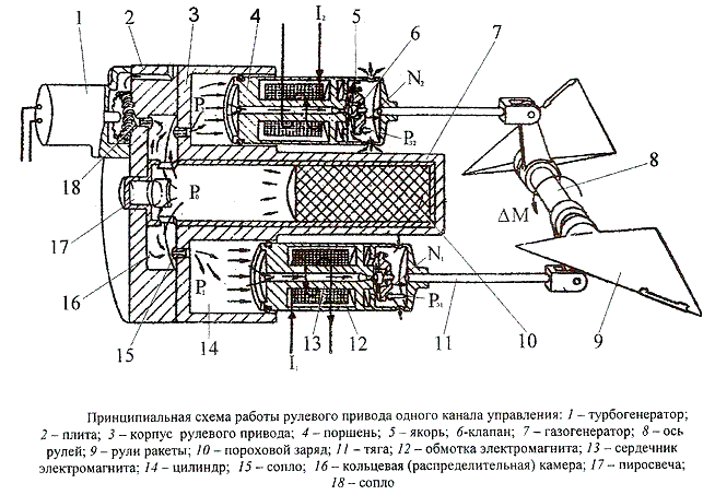
The steering unit is powered by hot gas generated by a powder gas generator (PGD). Its operation starts when you press the "Start" button on the carrier airplane. The current impulse goes to the gun 17, ignites the igniter, which in turn ignites the powder charge 10 of the gas generator 7. The resulting gases fill the ring distribution chamber 16, from where the gases through four nozzles 15 enter the working cylinders 14, putting pressure on the pistons 4. From the piston cavity gases pass through the hole in the core 13, the adjustable gap between the valve 6 and the end of the core 13 and further through the radial holes flow into the atmosphere.
The energy of the powder gas generator is also used to power the turbo generator 1, which supplies power to the rocket units. For this purpose, part of the gases from chamber 16 through nozzle 18 enters the blades of turbine generator 1 and further through the nozzle in the stove 2 is released into the atmosphere. The piston 4 of working cylinder 14 is simultaneously an electromagnet with winding 12. It is equipped with a valve device consisting of a calibrated hole in the core 13, anchor 5 and valve 6. By means of the valve device it is possible to control the gas flow rate through the working cylinder, and therefore, the value of the gas pressure acting on the piston. The position that the valve occupies is determined by the equality of two forces applied to it: the force of the electromagnet attracting anchor 5 and the gas dynamic force depending on the gas pressure. When the current changes in the electromagnet winding, the force that attracts the armature changes and the valve equilibrium can only come to a new position with a different gap between the valve and the core and, therefore, with a changed cylinder pressure.
If the currents I1 and I2 in the windings of both solenoids of the same control channel are equal, the flow through the valve devices of both pistons is the same. In this case, the pistons are stationary. When the HRC control signal is applied, the resulting difference in current causes a differential gap change in the valve devices of the two pistons. As a result, the equality of pressure in cylinders 14 and the equality of moments applied to the shaft of the steering is violated. The torque difference of the two pistons is proportional to the current difference. The rudders are rotated until they are balanced by the aerodynamic torque.
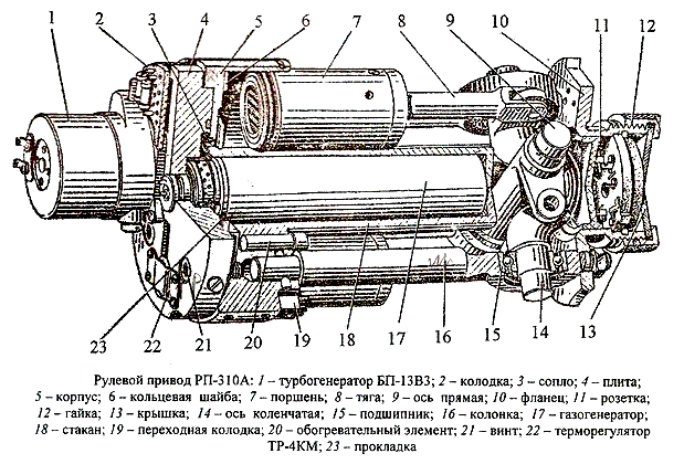
The main elements of the steering drive are: housing 5, four columns 16 with axes mounted in them 9 and 14 rocket rudders, flange 10, two pairs of pistons 7, gas generator 17, four heating elements 20. Columns 16 are inserted into the apertures of the case 5 and fixed with pins. On the opposite side of the column is fixed with four nuts flange 10 with socket 11, designed to connect the plug safety executive mechanism (PIM) contact fuse. Nut 12 is used to attach the PIM. On the front side to the body 5 is attached to the four screws 21 plate 4. Inside the glass 18, made for one whole with the case, there is a gas generator 17. Turbo generator 1, thermo regulator 22 and adapter block 2 are attached to plate 4. Heating elements 20 are placed in the holes of the body 5 and are used to heat the powder charge of the gas generator and cylinder, in which pistons 7 are mounted. The temperature of heating is regulated by a thermo regulator 22. Soldering of heating element wires is carried out on transition blocks 19. Pistons 8 connect pistons 7 with axle levers 9 and 14. Axis 9 is straight and axle 14 is cranked. Axes are rotated in bearings 15, pressed into columns 16. The gas distribution chamber is formed by a bore in plate 4. It communicates with the cylinders in which ring washers 6 are installed, due to which the powder gases are directed to the central part of the piston ends, which protects the piston O-rings from burnout. There are two radial channels in plate 4, which communicate with the gas distribution chamber. One of these is covered by a copper foil diaphragm that breaks when the gas pressure rises above the permissible level. The second one is used for compressed air supply during ground inspections of the control compartment.
Technical specifications
| Type of steering gear | gazoelectric |
| Powder gas pressure in the distribution chamber, N/m2 | 56-84 |
| Maximum steering angle | ±18° |
| Maximum torque developed by the drive via one control channel, Nm | 93 |
| Powder charge combustion time of gas generator, s | not less than 21 |
| Voltage produced by the turbine generator, B | 140-180 |