The Homing Thermal Head is a passive head that reacts to the target's thermal radiation. It has the following functions:
- captures and escorts the target at any time of the day outside the cloud and at an angle of at least 20° to the Sun;
- generates a control signal to point the missile at the target;
- gives this signal to the actuators of the control system.
Thermal radiation from the target is focused by the head's optical system into a spot (thermal image of the target) of small diameter. A modulating disc is mounted in the focal plane of the optical system. The optical system and the modulating disc are mounted on the gyroscope rotor and rotate with it. As long as the optical axis of the head does not coincide with the target sighting line, the modulating disc acts as a breaker, transforming the continuous thermal radiation of the target into "packs" of pulses that follow each other at the speed of the modulating disc. The deviation of the heat spot from the centre of the modulating disc depends on the angle between the head axis and the sighting line (angle of mismatch). The disc is designed so that the amplitude of the thermal energy pulses passing through it is proportional to this deviation.
The second coordinate of the target relative position (phasing angle) determines the angle position of the heat spot on the plane in which the modulating disk rotates and, consequently, the phase of the modulated target heat radiation.
The amplitude and phase modulated flow of thermal energy enters the photoresistance mounted behind the modulating disc. The photo resistivity converts this flow into an electrical signal called the mismatch signal. From the photo impedance, the mismatch signal is fed to the amplifier input and then to the THC gyro correction coils. Variable current flowing through these windings creates a moment, under the influence of which the gyroscope, and with it the optical system with modulating disk precedes in the direction of reducing the deviation of the THC optical axis from the target sighting line. Thus, a closed circuit of automatic angular tracking of the target is obtained. A mismatch signal in this loop plays the role of negative feedback. The same mismatch signal is also used to control the missile's flight. For this purpose, resistances are connected in series with the correction coil windings, the voltage drop on which from the correction current serves as an input signal for the coordinate converter. With the help of the latter, the alternating voltage is rectified and expanded into two components in two mutually perpendicular planes, structurally combined with the rudder planes of the 1st and 2nd rocket control channels.
Then two magnetic amplifiers convert the signals of the coordinate transducer in the control currents acting on the steering drives of the rocket. The rocket under the influence of aerodynamic moment arising from the movement of the rudder, turns in the right direction, focusing on the target.

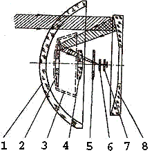
The optical system of the head is mirror-lens and is designed to capture and focus the thermal radiation of the target in the plane of the modulating disk. The casing 1 is rigidly connected to the head housing and is part of a hollow sphere. The other elements of the optical system (except for photoresistance) are rigidly connected to the gyro rotor and rotate with it. The photoresistivity 7 is fixed in the inner ring of the gyroscope and tilts with the ring at the head tracking angles to ensure that the photoresistivity surface remains perpendicular to the optical axis. The spherical mirror 8 is made of optical glass and has external aluminizing. The lens holder 4, being an element of the optical system, simultaneously serves for attaching the flat mirror 2 and the hood 3 to the gyro rotor. The lens hood 3 covers lens 4 from direct rays (besides rays coming from the mirror 2), protecting the photo resistance from direct light. Aperture 5 reduces glare and improves image quality in the plane of the modulating disc. The modulating disc is designed to modulate the thermal radiation of the target coming into the photo resistance. Thanks to the modulating disc, the mismatch signal produced by the homing head carries information about the target angular coordinates: mismatch angle and phasing angle.
As a receiver of target heat radiation, converting this radiation into electrical signals, the head uses sulfur-lead photoresistance. It has a maximum sensitivity to heat flux with a wavelength of 2.4 -2.5 µm. Before the photoresistivity there is a germanium optical filter that retains all beams with a wavelength of up to 1.8 µm, including the visible part of the spectrum. Under the action of radiant energy there is a change in the electrical conductivity of photoresistance. The voltage drop on the variable resistance is amplified by an electronic amplifier consisting of several cascades. The amplifier also includes two filters. One of them is set to the carrier frequency fn=800Hz, the second to the envelope frequency 66Hz. Each filter transmits electrical signals only to the frequency it is tuned to. This allows a weak mismatch signal to be highlighted against a general background of interference. The loads of the amplifier are the correction coils of the gyro system and the coordinate converter. The coils force the gyro to precess in the direction of the target. The voltage removed from the electronic amplifier contains information about the relative position of the target in the spherical coordinate system associated with the missile. The signal parameters that determine the coordinates of the target are its amplitude and phase. Since the missile is controlled by a rudder system located in two mutually perpendicular planes, the control signal from the polar coordinate system must be converted into a rectangular, rigidly connected to the rudder planes. The function of decomposition of the control signal into components is performed by a coordinate converter. The transducer is an electronic sine-cosine unit which consists of two identical parts serving the 1st and 2nd control channels. The operation of the coordinate transducer is based on the comparison of the mismatch signal phase with the phases of the two reference voltages. Reference voltages are produced by special generators (GON), which are part of the gyro system. Control signals from the coordinate transducer are fed to two identical magnetic amplifiers. Their purpose is to amplify the control signals to a level of power sufficient to operate the steering drives.
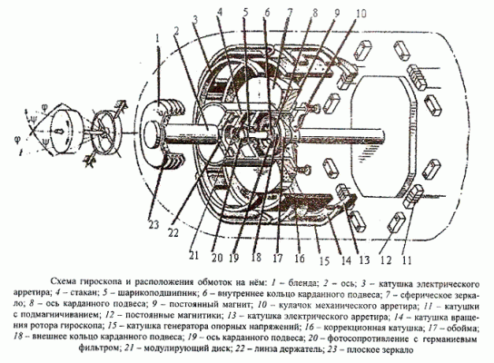
The homing head gyro system is a three-stage gyro sensor with correction. It is an integral part of the target tracking channel. The rotor of the gyroscope is a permanent magnet of 9 elliptical shape moving in an alternating magnetic field, reinforced in a cardan suspension. The inner ring of the 6 cardan suspension is the inner frame of the gyro, while the outer ring is the outer frame of the 10 gyroscope. The rotation of the inner ring by an angle provides the magnet with freedom of movement in one plane (rotation around the missile's transverse axis), by an angle - in another plane (rotation around the second transverse axis). In addition, the magnet, being mounted on two ball bearings 5 pressed on the axis connected to the inner ring of the cardan suspension, has the ability to rotate in the third plane (own rotation of the gyro). Together with the magnet, the mirrors 7 and 23 mounted on the common axis of the optical system and the modulating disc 21 rotate. The photoresistivity 20 is fixed in the inner ring of the 6 cardan suspension and can therefore rotate relative to the missile body by angles and .
The control elements of the gyroscope are located on a fixed frame. These include:
- four coils 14, which create a rotating magnetic field that interacts with the permanent magnet, causes the gyro to rotate. The motor generated by this pattern is synchronous. The coils are powered by the carrier plane. After starting the rocket, the gyroscope rotates by inertia.
- Four coils 11 with magnetization, serving to start the gyroscope and stabilize its rotation.
- Two cylindrical coils 3 and 13, playing the role of an electrical artillery. The purpose of the artillery is to keep the axis of the gyro system (hence the axis of the homing head) in the position coinciding with the axis of the rocket until the end of the "zeroing" section. When the rotor axis of the gyroscope deviates from the longitudinal axis of the rocket in coils 3 and 13, the permanent magnet 9 induces the EMF fed into the amplifier. From there the voltage is fed to the correction coil 16, the magnetic field of which interacts with the field of the permanent magnet, returns the rotor to its original position.
- Four coils of 15 reference voltage generators. The coils are arranged in a 90° shift, one relative to the other, and the opposing coils are connected. When the windings cross the power lines of the magnetic field of the permanent magnet, the EMFs are guided into each other by 90° phase shift. These EMFs are used in the coordinate converter.
- The correction coil is 16 cylindrical in shape. The coil is connected to the output of the electronic amplifier. The current flowing along the coil, caused by a mismatch signal, creates a magnetic field that forces the permanent magnet 9 (gyro rotor) to rotate (precess) around the cardan suspension axes 8 and 19. In doing so, the optical axis of the homing head turns towards the target.
Tactical and technical characteristics
| Maximum range of target acquisition (IL-28 type) at an altitude of more than 15 km with a 0/4, m angle. | 7600 |
| Threshold sensitivity | not exceeding 0.03 mW/cm2 |
| Tracking field, in which the selected target is escorted (cone with an angle at the apex) | 50° |
| Full axle angle TGSN | ±28° |
| Head clamping field (cone with angle at top) | 3°30’ |
| Gyroscope rotor speed, rpm - when power is turned on - 21seconds from the moment the power is turned on |
72±5 not less than 50 |
| Continuous operating time TGSN, min. - outsourced - powered by the onboard generator |
120 around 6 |
| Focal length of optical system, mm | 84.3 |
| Weight, kg | 5.2 |
| Overall dimensions, mm - diameter - length |
127 320 |

