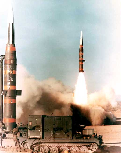
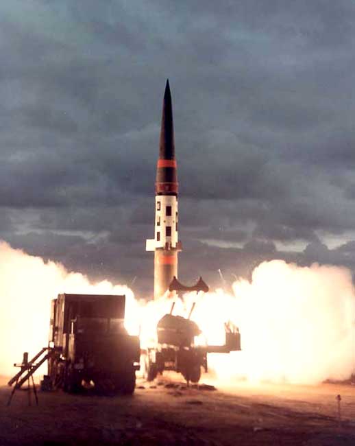
The Pershing-1 operational-tactical missile was intended for use by large military formations to shoot at cities, airfields, military warehouses, congregations of troops and enemy launchers. Designed to replace a Red stone missile of similar purpose.
The main developer - the company Martin Marietta (USA Orlando, Florida).
Stand testing of the Pershing-1 missile began in late 1958, flight testing - in February 1960. In April 1963, entered the military testing of the A-battery of the 2nd Division, 44th Artillery Regiment of the U.S. Army.
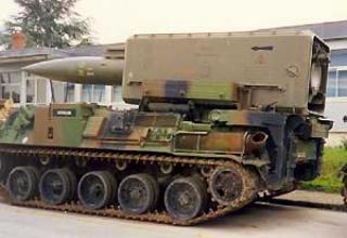
Immediately after the adoption of Pershing missiles, the U.S. Army command began to modernize them and improve the organizational structure of the missile units. The main goal of the modernization was to reduce the vulnerability of the missile system by improving its mobility, transportability and combat readiness in general. The improved missile system was named Pershing-1A. The Pershing-1A development program was approved in 1965 and in 1969 the missile was adopted for service. Pershing-1A replaced the Pershing-1, which was produced from 1964 to 1969. High mobility of the complex was achieved due to the location of all its elements on wheeled vehicles, and the combat readiness was increased by improving the testing and launching equipment of the complex and automation of missile preparation and launch.
In 1984, the U.S. Army began to receive a modernized Pershing-2 system, characterized by increased range and accuracy of fire.
The latest Pershing-1A rocket systems were destroyed in 1989 in accordance with the Treaty between the USSR and the United States on the Elimination of Medium and Short Range Missiles (MRMS).
Composition:

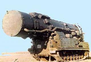
The rocket and ground equipment of the Pershing-1A system are transported on a cargo semi-trailer towed by a wheeled tractor and on three off-road vehicles SM-274 (XM-274) (see composition of the complex). On the platform of the semitrailer there is a launch table, the installer with the rocket (both stages and instrument compartment) and the head part of the rocket, fully ready for docking with the rocket. On one vehicle SM-274 mounted fire battery command post, on the other - the power plant and station for pre-launch inspection and control of launch, and on the third - a radio station with power supply installation. The radio is equipped with two antennas - inflatable parabolic and retractable telescopic.
The starter unit of Pershing-1A system together with an air transport missile can be airlifted by C-130 military transport aircraft and larger transport aircraft of other types.
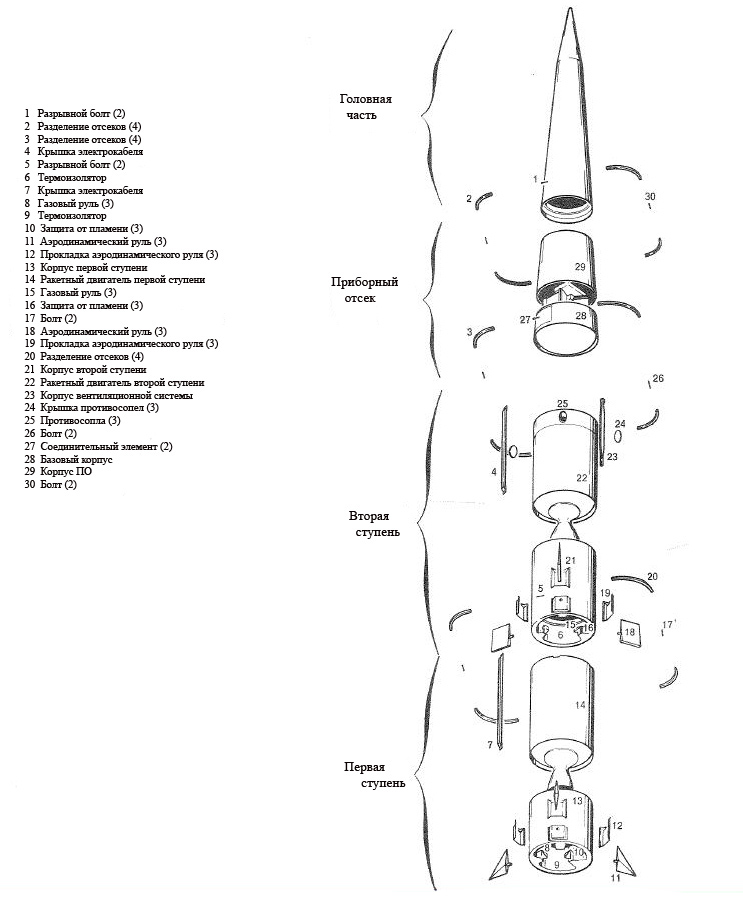
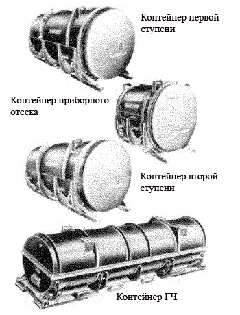
Structurally and functionally, the missile consists of 4 compartments: head unit, instrument compartment, second stage engine, first stage engine. Each compartment had its own storage and transport container (see diagram).
Payload - monoblock nuclear warhead (60, 200 or 400 kt) is placed in the second stage head unit. The shape is conical, 3.9 m long and 0.72 m in diameter.
The body of the head unit was made on an aluminium base and had a heat-proof plastic shell of variable thickness. The plastic shell was covered with randomly oriented and impregnated asbestos tapes connected to a homogeneous structure under the influence of temperatures and high pressure. The variable thickness of the shell was chosen to be in line with the ablation rate of the head end when it returns to the atmosphere when it is exposed to high temperatures.
The connection between the head end and the instrument compartment was made by means of a breakaway bolt.
The instrument compartment of the stringer-span type has the form of a truncated cone, on the frame is placed the on-board equipment (see diagram). The bottom of the compartment is removable to provide access to the control equipment and the possibility of its installation. On the side surface there is a sighting window, made of optically transparent material, which is necessary to aim the missile before launch. The instrument compartment contains: measuring block-gyrostabilized platform ST-120, on-board digital computing device, amplifying-converter equipment and power supply. There was also a cylinder with compressed air and a high pressure air supply system.
In the control system, the ST-120 platform provided information about the speed of the rocket and its position, based on these data the on-board computer calculated the deviations from the given trajectory and generated control signals. The commands could be decomposed into separate control elements (gas and aerodynamic rudders).
The on-board power sources are a battery and a 0.75 kW rotary converter.
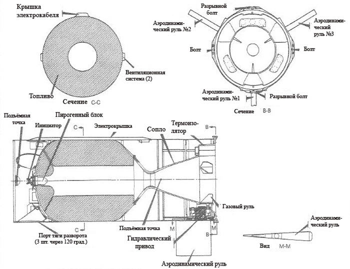
The second stage motor consisted of the housing, the connection compartment and the aft. The motor casing was made of high-strength D6AC steel. The connection compartment at the front of the casing was used for docking to the instrument compartment.
The first stage engine of the M-105 had a similar design, but was larger.
The difference between the second stage and the first was that the second stage had a pulse control system, which consisted of three elements located 120° apart. This system reduced the traction of the second stage at a given time and provided effective separation of the head end.
The ventilation system contained two charge locks, which were attached to the outer horizontal axis of the second stage. Two rectangular holes were made in the casing and the fuel right behind the pulse control system, which allowed the fuel combustion products to escape into the environment, thus reducing the impact of the second stage engine on the head end.
The aft part of the engine included three gas steering wheels, three aerodynamic steering wheels, three hydraulic drives and an ignition screen.
The solid fuel charge was made of aluminium powder as a fuel, ammonium perchlorate as an oxidizer and polybutadiene (essentially artificial rubber) as a binder and fuel. The designation PBAA/AP/Al. The composition of the charge ensured long-term storage. Burning was carried out through an inner channel of cylindrical shape. The fuel was developed by "Thiokol" company.
The engine was ignited by a pyrogen block, which in turn was ignited by initiators and a small pyrotechnic charge. The pyrogen block was a miniature rocket engine, the combustion products of which went into the engine combustion chamber and thus heated the fuel in stages to a temperature at which it began to burn.
The second stage engine nozzle had an average expansion coefficient of 15.06 and was made of steel rings with a glass-fibre shell.
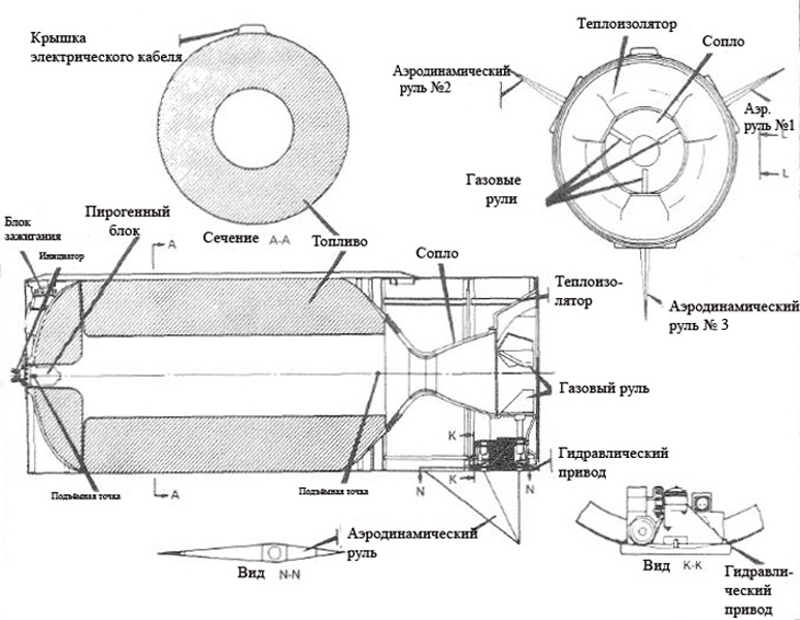
The first stage solid fuel engine M-105 is a lightweight steel case with a fuel charge (based on polyurethane) weighing about 2450 kg, an igniter and a nozzle. The construction materials, fuel composition and solutions for the first stage engine were almost exactly the same as for the second stage engine. Nozzle with an average coefficient of expansion of 7.06, was made by technology similar to the second stage engine nozzle.
The engine housings of both stages were mass produced by International Manufactoring.
The rocket uses inertial control system "Bendix" (autonomous), equipped with gyroscopes with two degrees of freedom on gas bearings. Its function is to compare a pre-calculated program trajectory with the actual trajectory determined in flight, taking into account the current coordinates, and develop appropriate guidance signals.
The executive bodies of the control system are the aerodynamic rudders in combination with the gas rudders. Each pair of air and gas rudders is operated by one hydraulic drive. The rocket is equipped with 4 aerodynamic rudders, located in the stabilization planes. The axles of rotation of the rudders are perpendicular to those of the rocket. The II-IV rudders are connected to each other. When they are deflected together there is a force that controls the movement of the rocket on the pitch. Rudders I-III are used to control the flight on course and roll, working in the first case synchronously, in the second - in different directions.
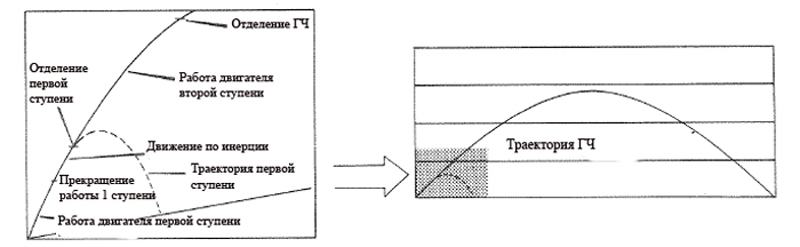
When detached from the launch table, the rocket control is transferred to the inertial control system, and communication with the firing position is not maintained. The first stage is separated at an altitude of 12 km, when the set speed is reached, by instantly lowering the pressure in the combustion chamber (see diagram). When the first stage engine is separated, the second stage engine is started. The operating period of the rocket's second stage engine varies and depends on the range of the target location. When the appropriate flight speed and location of the missile are achieved in space, the head end is separated from the second stage and continues to fly to the target along a ballistic trajectory.
Characteristics:
| Range, km | 185 - 740 |
| End height of the active section, km | 45 |
| The length of the rocket, m | 10,5 |
| Starter weight, kg | 4660 |
| The diameter of the rocket, m | 1 |
| Weight of the first stage engine, kg | 2450 |
| Operating time of the first stage RDTT, s | 40 |
| Second stage engine weight, kg | 1640 |
| Mass of HF, kg | 330 |
| Trotile equivalent charge, kt. | 40, 200, 400 |
| Number of warheads | 1 |
Testing:
For the main organizational unit of the Pershing-1A missile system was adopted a division, which has 4 fire batteries (9PU each), as well as a staff battery and a maintenance battery. The number of personnel is 1368 people.
The U.S. Army created 4 divisions Pershing-1A, 3 of which were permanently located in Germany and were part of the 56th Brigade with headquarters in Schwebisch-Gmund (55 km east of Stuttgart). The 1st division of the 41st Art Regiment was also stationed in Schwebisch-Gmund, the 1st division of the 81st Art Regiment in Neu-Ulm, the 3rd division of the 84th Art Regiment in Neckarzulm and Heilbronn, the 3rd division of the 9th Art Regiment in Fort Sill (Oklahoma, USA).
The 56th Brigade had a total of 108 Pershing-1A guided missiles. Until the end of 1983, they were one of the main operational and tactical means of the U.S. Army to conduct nuclear strikes in the interests of the NATO DIA at the European theater of war.
Sources:
- Pershing 1A System Description, Martin Marietta Aerospace
- "Зарубежное военное обозрение" №7(с.17-20), 1985; №6(с.48-50) , 1973.
- "Техника вооружения за рубежом" №16(с.1-2) , 1969;№3(с.5) , 1975; №15(с.1-5) , 1969; №15(с.2) , 1972; №16(с.1-3) , 1967.
- "Военная авиация и ракетная техника" №5(с.21-22),1964; вып.21(с.6-11), 1963;№19(с.10-12), 1961.
- "Военная техника" №7(с.21-24), 1962; №20(с.11-12), 1961; №20(с.11-12) , 1961.
- "Техника и вооружение сухопутных войск капиталистических государств" №1(с.3) , 1985; №14, 1976.
- "Техника и вооружение" №5(с.83-85) , 1961.